Arduino Tutorial
Get Started with Arduino
Installing Arduino IDE
When you get control board, you need to download Arduino IDE and driver firstly.
You could download Arduino IDE from the official website:
https://www.arduino.cc/, click the SOFTWARE on the browse bar, click“DOWNLOADS” to enter download page, as shown below:
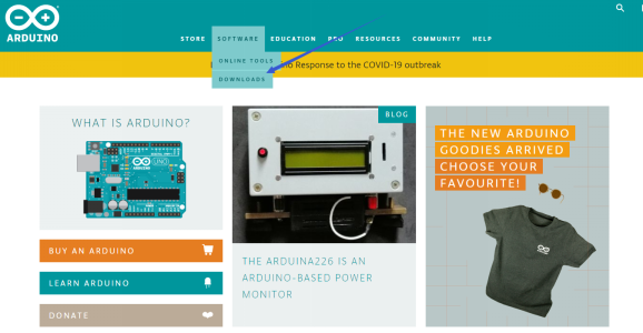
There are various versions of IDE for Arduino. Just download a version compatible with your system. Here we will show you how to download and install the windows version of Arduino IDE.
There are two versions of IDE for WINDOWS system. You can choose between the installer (.exe) and the Zip file. For installer, it can be directly downloaded, without the need of installing it manually. However, for Zip package, you will need to install the driver manually.
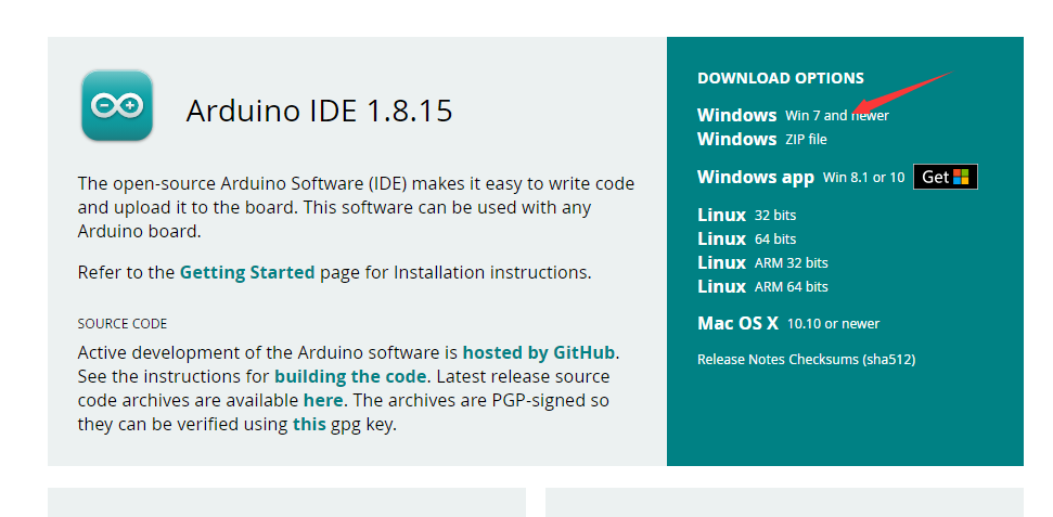
Click JUST DOWNLOAD.

The Control Board of Kidsbits
This control board based on Arduino integrates ultrasonic and line-tracking functions and boasts two passive buzzers to play music and an LED display
Chip |
ATMEGA328P-AU |
|---|---|
Working Voltage |
5V |
Working Current |
Power by computer via USB cable or by power supply with output capacity greater than or equal to 2A |
Maximum Power |
Maximum output power is 10W |
Working Temperature |
0-50 degrees Celsius |
Size |
77.5*75mm |
Environmental Attribute |
ROHS |
Install the Driver of the board
Let’s install the driver of the main board.
The procedures to install the driver may have slight differences for different systems. Here we will take Win7 system as as example to illustrate how to install the driver.
The USB to serial port chip of this control board is CH340G. So you need to install the driver for the chip. You can click the driver file here https://kd.kidsbits.cc/KD0003-Driver to download it.
In different systems, the driver installation is similar. Here we start to install the driver on the Win7 system.
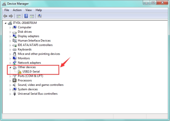
Plug one end of your USB cable into the square interface of the kidsbits coding box and the other into a USB socket on your computer.
When you connect the kidsbits coding box to your computer at the first time, right click your“Computer” —>for “Properties”—> click the “Device manager”, under Other devices, you should see the “USB2.0-Serial”.
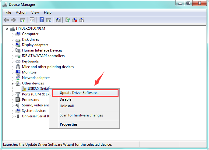
 Then right-click on the
USB2.0-Serial and select the top menu option (Update Driver Software…) shown
as the figure below.
Then right-click on the
USB2.0-Serial and select the top menu option (Update Driver Software…) shown
as the figure below.
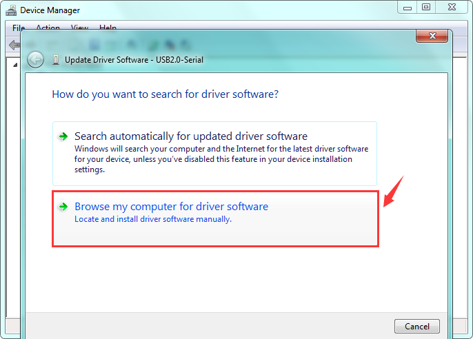
Then it will be prompted to either“Search Automatically for updated driver software or“Browse my computer for driver software”. Shown as below. In this page, select“Browse my computer for driver software”.
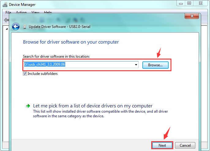
After that, select the option to browse and navigate to the “drivers” folder of usb-ch341 installation.
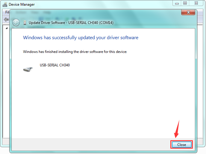
Once the software has been installed, you will get a confirmation message. Installation completed, click“Close”. http://wiki.keyestudio.com/index.php/File:Driver_6.png
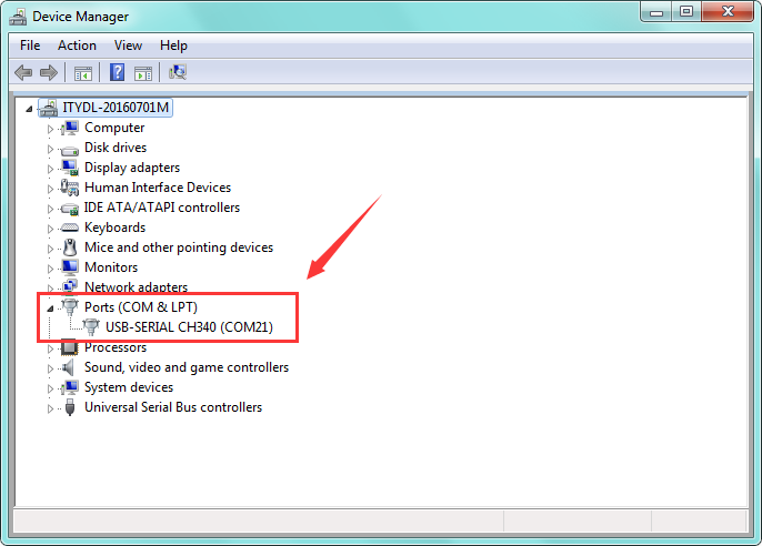
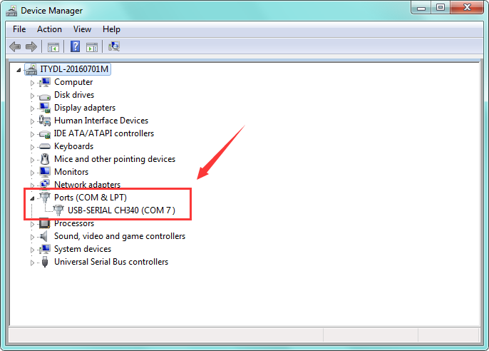
Up to now, the driver is installed well. Then you can right click“Computer” —>“Properties”—>“Device manager”, you should see the device as the figure shown below.
Arduino IDE Setting
Click icon,and open Arduino IDE.
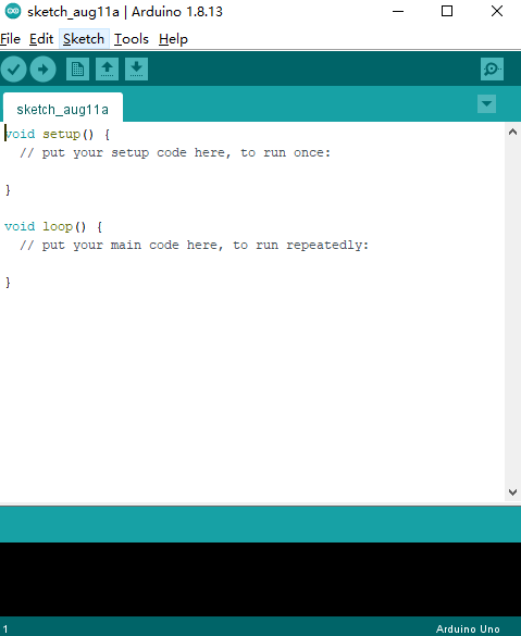
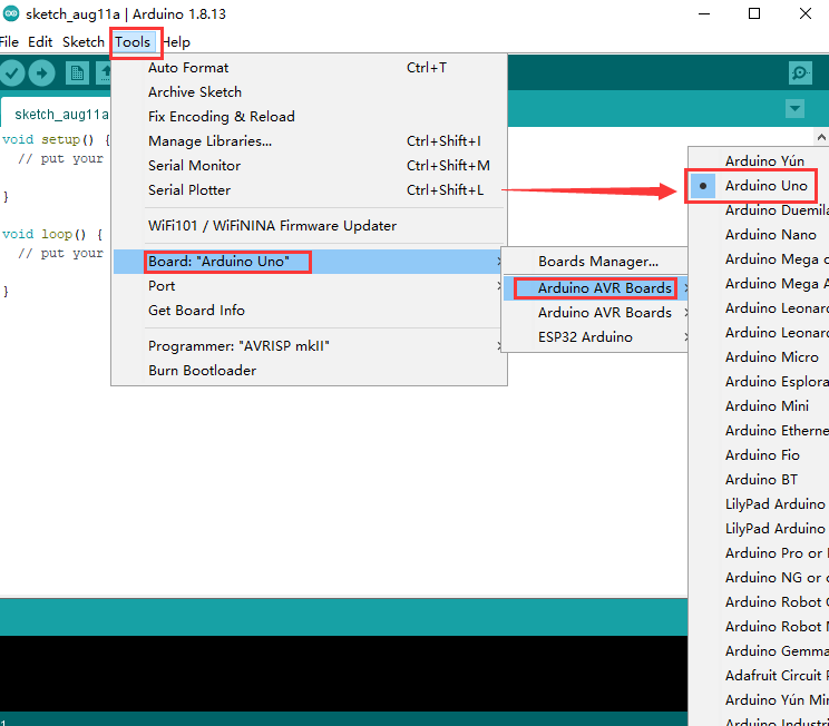
When downloading the sketch to the board, you must select the correct name of Arduino board that matches the board connected to your computer. As shown below;
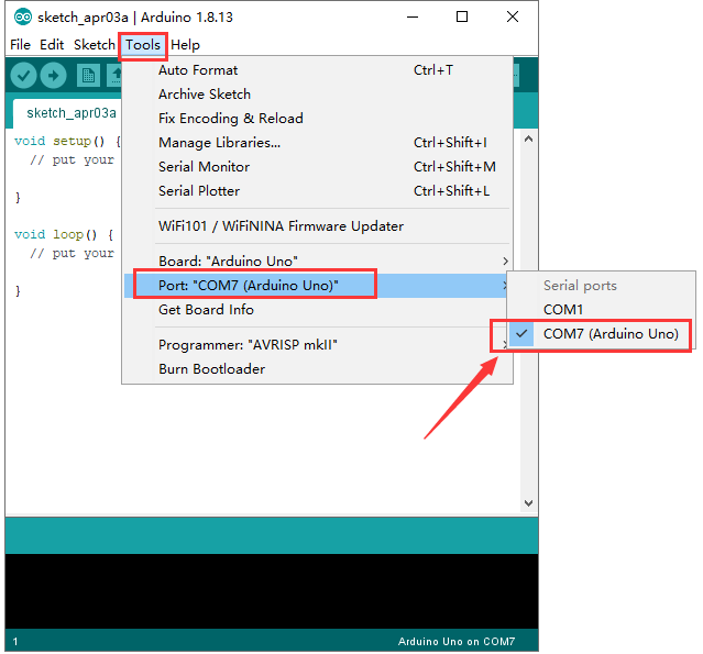
Then select the correct COM port (you can see the corresponding COM port after the driver is successfully installed)
The functions of these symbols are demonstrated below.
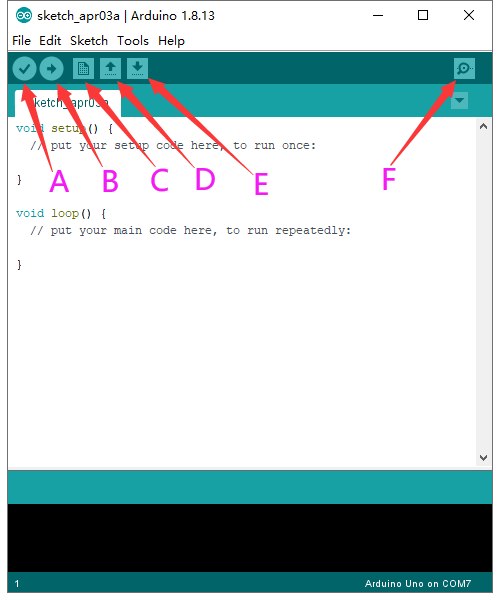
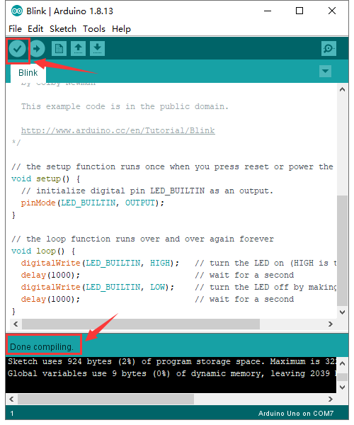
A- Used to verify whether there is any compiling mistakes or not.
B- Used to upload the sketch to your Arduino board.
C- Used to create shortcut window of a new sketch.
D- Used to directly open an example sketch.
E- Used to save the sketch.
F- Used to send the serial data received from board to the serial monitor.
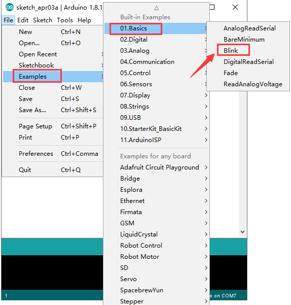
(5)Start First Program
Open the file to select Example, and click BASICS→BLINK, as shown below:
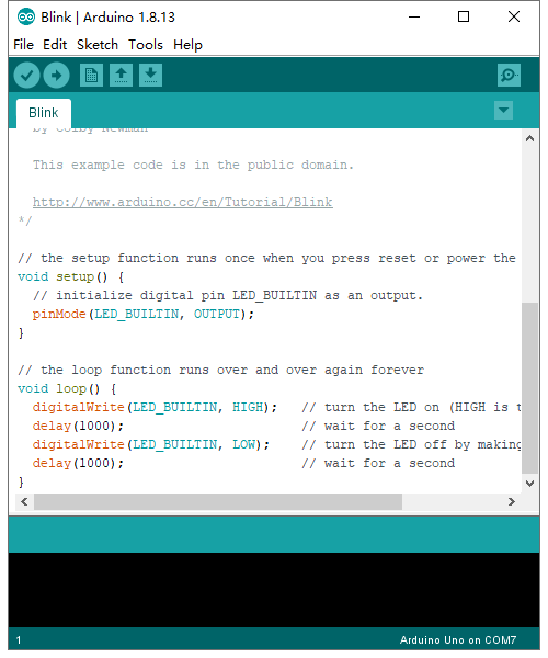
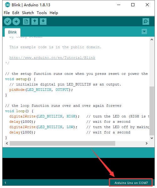
Set the correct COM port, and the corresponding board and COM port are shown on the lower right of IDE.
Click to start compiling the
program, and check errors.
to start compiling the
program, and check errors.
Click to upload the program
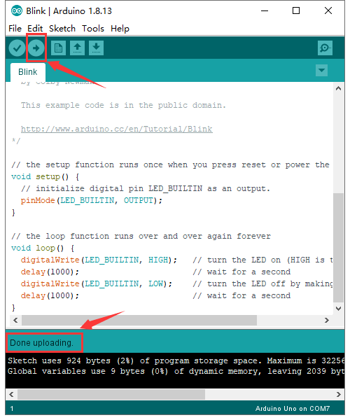
After the program is uploaded successfully, the onboard LED blinks. Congratulation, you have finished the first program.
How to Add Libraries?
(1)What are Libraries ?
Libraries are a collection of code that makes it easy for you to connect to a sensor,display, module, etc.
For example, the built-in LiquidCrystal library helps talk to LCD displays. There are hundreds of additional libraries available on the Internet for download.
The built-in libraries and some of these additional libraries are listed in the reference.
(2)How to Install a Library ?
Here we will introduce the most simple way for you to add libraries .
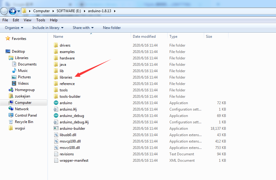
Step 1:After downloading well the Arduino IDE, you can right-click the icon of Arduino IDE.
Find the option “Open file location” shown as below:

Step 2: Enter it to find out libraries folder, this folder is the library file of Arduino.
Step 3: Next to find out the“libraries”folder of the yellow robot(seen in the link: https://kd.kidsbits.cc/KD0003), you just need to replicate and paste it into the libraries folder of Arduino IDE.
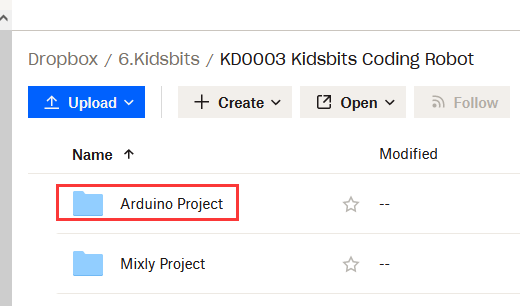
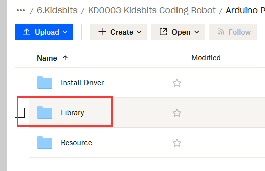
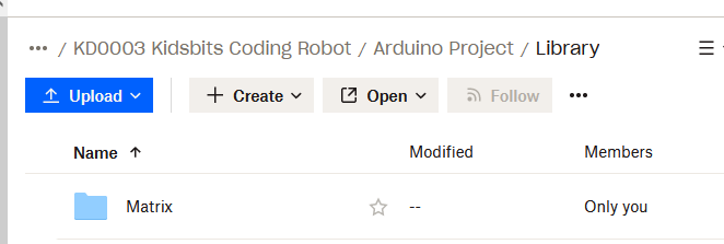
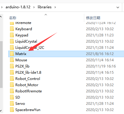
Then the libraries of yellow robot are installed successfully, as shown below:
Projects:
The whole project begins with basic programs. By assembling the robot car, you will absorb the knowledge of electronics and machinery step by step. I reckon that you can hardly sit still and itch to have a go now. Let’s get started.
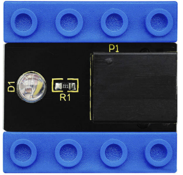
Project 1: Blinking LED
Introduction:
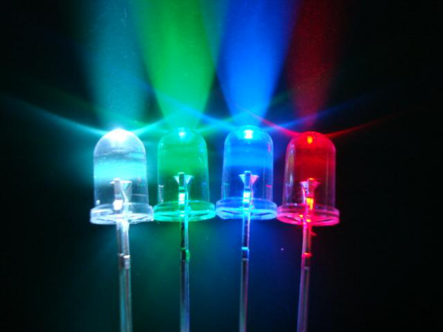
For starters and enthusiasts, LED Blink is a fundamental program.
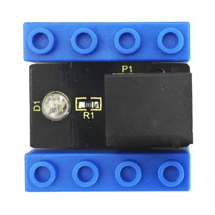
LED, the abbreviation of light emitting diodes, consists of Ga, As, P, N chemical compound and so on. The LED can flash diverse color by altering the delay time in the test code. In the circuit, power on GND and VCC, the LED will be on if S end is high level; nevertheless, it will go off.
In the experiment, we make the LED module blink through the test code.
(2) Specification:
Control interface: digital port
Working voltage: DC 3.3-5V
Port: EASY plug
LED display color: seven colors
(3) Connection Diagram
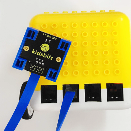
This Kidsbits programming blocks LED module is compatible with LEGO blocks and the yellow robot. To wire up easily, we adapt the EASY plug to hinder the reverse wiring-up. As shown below, we connect the LED module to the digital port 12(D12)
Test Code:
/*
kidsbits coding robot kit
Project 1
Blinking LED
http//www.kidsbits.cc
*/
int led=12;   //set to digital port
void setup()
{
  pinMode(led, OUTPUT);  //set led to OUTPUT
}

void loop()
{
  digitalWrite(led,HIGH);  //led outputs high levels, LED on
  delay(500);            //delay in 500ms
  digitalWrite(led,LOW);   //led outputs low levels, LED off
  delay(500);
}
Test Result:
Upload the code, the LED connected to D12 blinks circularly, with an interval of 500ms.
(6) Code Explanation:
int led=12; define as the digital port
pinMode(led, OUTPUT): This function can denote that the pin is INPUT or OUTPUT
digitalWrite(led,HIGH): When pins are seen as OUTPUT, set it to HIGH(output 5V) or LOW(output 0V)
delay(500); a delay function, 500 is the delay time, unit is ms
(7) Extension Practice:
We have succeeded in blinking LED. Next, let’s observe what will happen to the LED if we modify pins and delay time.
int led=12; //set to digital port

void setup()

{

   pinMode(led, OUTPUT); //set led to OUTPUT

}

void loop()

{

digitalWrite(led,HIGH); // led outputs high levels, LED on

delay(100); //delay in 100ms

digitalWrite(led,LOW); //led outputs low levels, LED off

delay(100);

}
The test result shows that the LED flashes faster. Therefore, we can draw a conclusion that pins and time delaying affect flash frequency.
Project 2: Playing Music
Introduction:
We can use Arduino to make many interactive works, of which the most commonly used is acoustic-optic display.
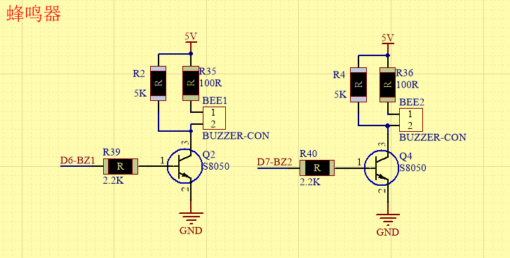
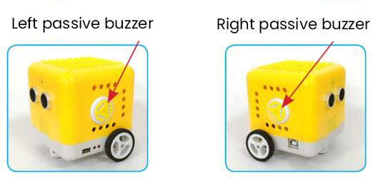
The buzzer we introduced here is a passive buzzer. It cannot be actuated by itself, but by external pulse frequencies. The passive buzzer doesn’t carry with vibrator inside, so it need external sine or square wave to drive. It can produce slight sound when connecting directly to power supply. It features controlling sound frequency and producing the sound of“do re mi fa so la si”.
Passive Buzzer:
2.1 Advantages:
Low cost
the sound frequency is high
In some experiments, passive buzzer and LED can use a IO port jointly.
2.2 How to use passive buzzer
Passive buzzer is controlled by PWM pulse width rather than tones.
PWM is a means of controlling the analog output via digital means. Digital control is used to generate square waves with different duty cycles (a signal that constantly switches between high and low levels) to control the analog output.In general, the input voltages of ports are 0V and 5V.
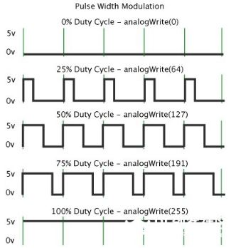
In the above figure, the green line represents a period, and value of analogWrite() corresponds to a percentage which is called Duty Cycle as well. Duty cycle implies that high-level duration is divided by low-level duration in a cycle. From top to bottom, the duty cycle of first square wave is 0% and its corresponding value is 0. The LED brightness is lowest, that is, light off. The more time the high level lasts, the brighter the LED. Therefore, the last duty cycle is 100%, which correspond to 255, and LED is the brightest. And 25% means darker.
PWM mostly is used for adjusting the LED’s brightness or the rotation speed of motors or the frequency of passive buzzer.
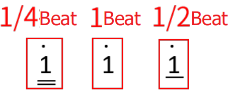
Beats are the time delay for each note. The larger the number, the longer the delay time. A note without a line in the spectrum is a beat, with a delay of 1000 milliseconds. while a beat with an underline is 1/2 of a beat without a line, and a beat with two underlines is 1/4 of a beat without a line.
Preparation:
Slide the Bluetooth switch under the yellow robot to OFF end
Interface the yellow robot with a computer via a USB cable.
Upload the code to Arduino IDE
3. Test Code:
Turn off the Bluetooth switch before uploading the code.
/*
kidsbits coding robot kit
Project 2
Playing Music
http//www.kidsbits.cc
*/
void setup(){
  pinMode(6, OUTPUT);
}
void loop(){
  tone(6,392);
  delay(125);
  tone(6,392);
  delay(125);
  tone(6,440);
  delay(250);
  tone(6,392);
  delay(250);
  tone(6,532);
  delay(250);
  tone(6,494);
  delay(500);
  tone(6,392);
  delay(125);
  tone(6,392);
  delay(125);
  tone(6,440);
  delay(250);
  tone(6,392);
  delay(250);
  tone(6,587);
  delay(250);
  tone(6,532);
  delay(500);
  tone(6,392);
  delay(125);
  tone(6,392);
  delay(125);
  tone(6,784);
  delay(250);
  tone(6,659);
  delay(250);
  tone(6,532);
  delay(250);
  tone(6,494);
  delay(250);
  tone(6,440);
  delay(250);
  tone(6,392);
  delay(125);
  tone(6,392);
  delay(125);
  tone(6,330);
  delay(250);
  tone(6,262);
  delay(250);
  tone(6,587);
  delay(250);
  tone(6,532);
  delay(500);
}
4. Test Result:
Upload the code to the yellow robot, you will hear the birthday song.
Code Explanation:
There are two important factors in music: pitch and beat
Frequency is made of a series of pitch names in English letters and Numbers. You can choose different frequencies, that is, tone. The frequency of sound is called pitch.
It involves music knowledge. In music lesson, our teacher taught“1(Do), 2(Re), 3(Mi), 4(Fa) , 5(Sol), 6(La), 7(Si)”
1(Do) |
2(Re) |
3(Mi) |
4(Fa) |
5(Sol) |
6(La) |
7(Si) |
|---|---|---|---|---|---|---|
C |
D |
E |
F |
G |
A |
B |
The number depends on high or low tone. The larger the number, the higher the tone. When the number is same, the frequency (tone) is getting higher and higher from C to _B.
Beats are the time delay for each note. The larger the number, the longer the delay time. A note without a line in the spectrum is a beat, with a delay of 1000 milliseconds. while a beat with an underline is 1/2 of a beat without a line, and a beat with two underlines is 1/4 of a beat without a line.
( )
)
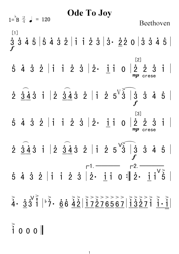
Here is the notation of Ode to Joy.
Project 3: Birthday Gift
Introduction:
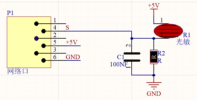
Under the weak light,the yellow robot will play a birthday song and blink its LED; however, it won’t play music and blink its LED under the strong light. Light and music can vary with light intensity! In this project, we particularly introduce the photoresistor module.
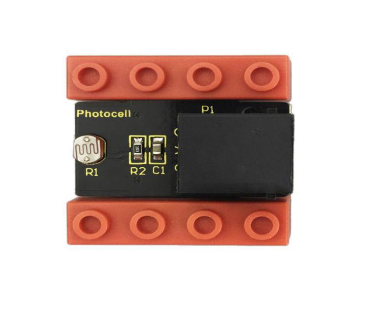
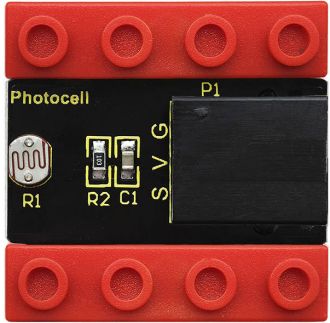
Photoresistor
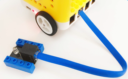
This photoresistor sensor integrates the LEGO building block and Easy Plug port, which can be fixed on the yellow robot flexibly. Only a blue cable needed can interface it with the yellow robot. You are free from worries over reversely wire up or damaging the module
This sensor is most sensitive to ambient light, generally used to detect the brightness of the ambient light and trigger a single-chip or relay module, etc.
It mainly uses photoresistive elements and changes with light intensity. Under the strong light, the resistance is 5-10KΩ; if there is no bright light, the resistance is 0.2MΩ.
Parameter:
Port:EASY plug
Working Voltage:DC 5V
Output Signal:Analog signal
Components:
Kidsbits Yellow Robot *1 |
Kidsbits Building Block LED Module *1 |
Kidsbits Building Block Photoresistor*1 |
|---|---|---|
|
|
|
When the ambient light is weak, LED will flash and the yellow robot will play songs
When the ambient light is strong, LED will be off and the robot won’t play music.
And we need to detect the ambient light firstly. According to the detected result, the light intensity value is between 700 and 750. Then we will continue to measure.
When light intensity is between 700 and 750. When covering the photoresistor, the detected value gets small. If the value is less than 700, robot will play music.
If you the intensity is 750, LED will be off and robot won’t play music.
Connection Diagram:
Note: the LED module is interfaced with D12 and the photoresistor module is connected to A6 port.
Test Code:
/*
kidsbits coding robot kit
Project 3
Birthday Gift
http//www.kidsbits.cc
*/
void setup(){
  Serial.begin(9600);   //Set the baud rate to 9600
  pinMode(6, OUTPUT);  //Set analog port A6 to output
  pinMode(12, OUTPUT);  //Set digital port 12 to output
}

void loop(){
  Serial.println(analogRead(A6)); //Read the analog value of A6
  if (analogRead(A6) < 700) {     //Judge whether the value of A6 is less than 700
    tone(6,392);               //A6 analog value is 392 pulses
    delay(125);                //delay
    tone(6,392);
    digitalWrite(12,HIGH);       //Digital port 12 outputs high level
    delay(125);
    tone(6,440);
    digitalWrite(12,LOW);       //Digital port 12 outputs low level
    delay(250);
    tone(6,392);
    digitalWrite(12,HIGH);
    delay(250);
    tone(6,532);
    digitalWrite(12,LOW);
    delay(250);
    tone(6,494);
    delay(500);
    tone(6,392);
    digitalWrite(12,HIGH);
    delay(125);
    tone(6,392);
    delay(125);
    tone(6,440);
    digitalWrite(12,LOW);
    delay(250);
    tone(6,392);
    digitalWrite(12,HIGH);
    delay(250);
    tone(6,587);
    digitalWrite(12,LOW);
    delay(250);
    tone(6,532);
    delay(500);
    tone(6,392);
    digitalWrite(12,HIGH);
    delay(125);
    tone(6,392);
    delay(125);
    tone(6,784);
    digitalWrite(12,LOW);
    delay(250);
    tone(6,659);
    delay(250);
    tone(6,532);
    delay(250);
    tone(6,494);
    digitalWrite(12,HIGH);
    delay(250);
    tone(6,440);
    delay(250);
    tone(6,392);
    delay(125);
    digitalWrite(12,LOW);
    tone(6,392);
    delay(125);
    tone(6,330);
    delay(250);
    tone(6,262);
    digitalWrite(12,HIGH);
    delay(250);
    tone(6,587);
    delay(250);
    tone(6,532);
    delay(500);
    noTone(6);
    digitalWrite(12,LOW);

  }
  if (analogRead(A6) > 750) {
    digitalWrite(12,LOW);
    noTone(6);

  }

}
Test Result:
Upload code. Under the weak light, the robot will blink its LED and play song; however, under the strong light, it won’t take a reaction.
Code Explanation:
Serial.begin(9600)-initialize the serial port, and the serial port rate is 9600
pinMode- define the mode of Pin as output or input
delay(500)-delay function; 500 is delay time, you can set delay time.
Project 4: Distance Detector
Description:
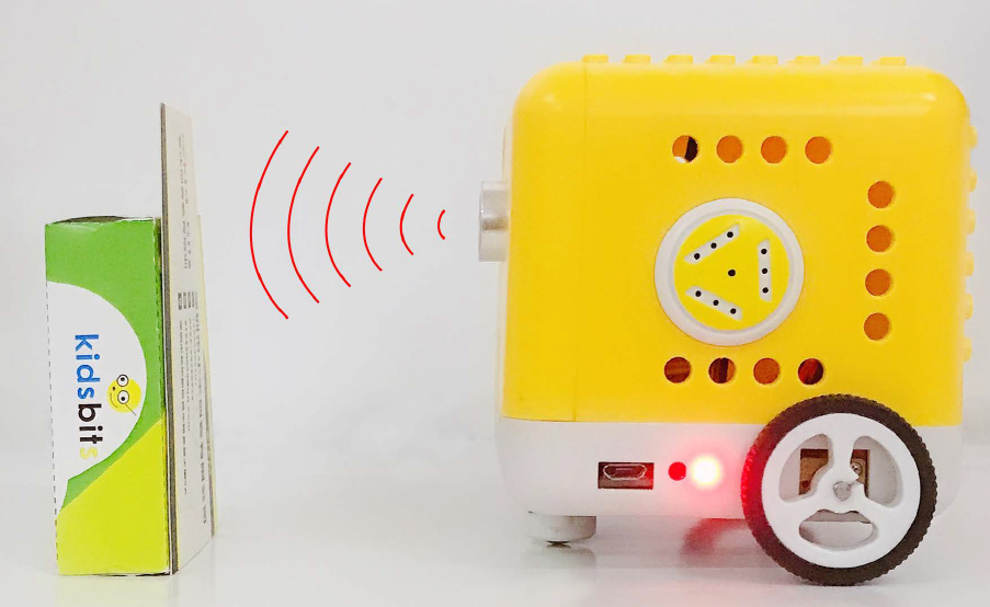
You may find that when we reverse a car, the alarm system will be triggered if the car is going to hit the obstacle behind. This is because the car has installed a safety device, the reversing radar which can detect the distance between the car and objects behind.
In this lesson, we will learn how to make such a distance measuring device with an ultrasonic sensor and a buzzer. Since we have illustrated buzzer in previous project, here we will focus on the ultrasonic sensor.
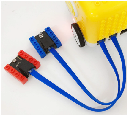
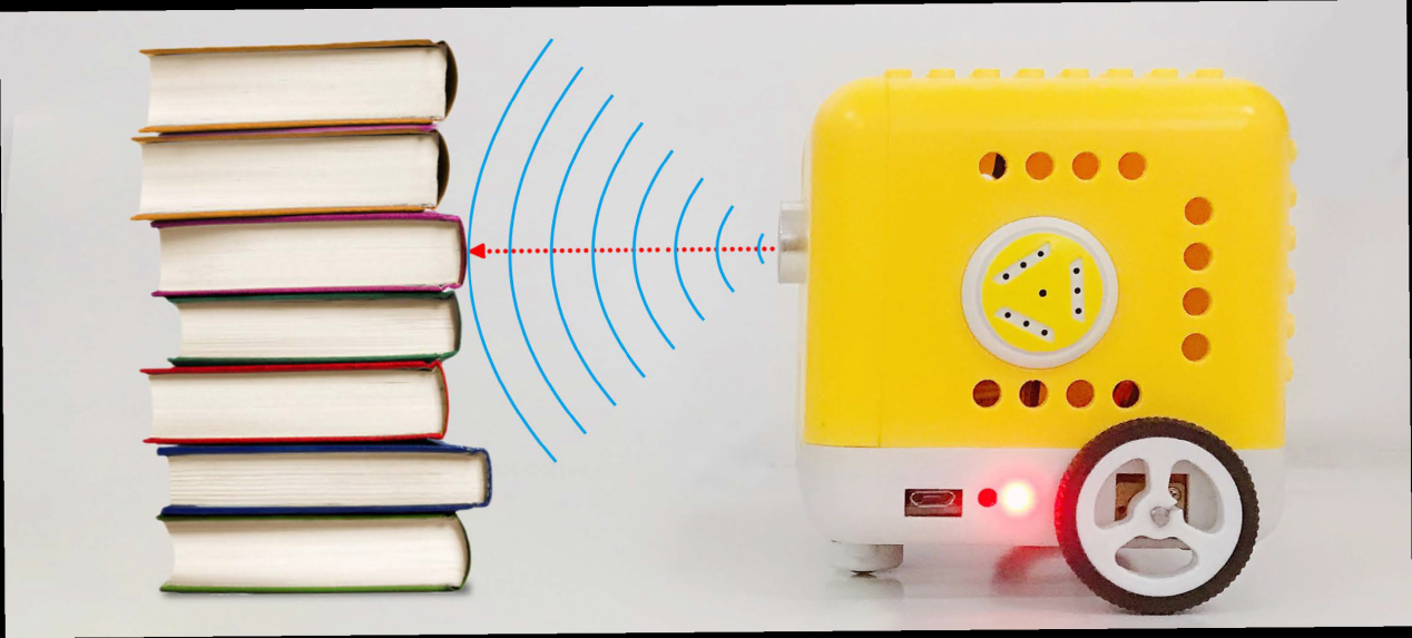
Ultrasonic Module
An ultrasonic sensor uses a sonar to determine the distance from the object like what bats do. And it boasts a complete transmitting module and a receiving module. Thus it can provide a non-contact distance measurement with high accuracy and stable readings.
Ultrasonic sensors have found wide applications in all sorts of electronic projects, such as obstacle detection and distance measurement. This project will concentrate on how to use the ultrasonic sensor to detect distance.
Working principle:
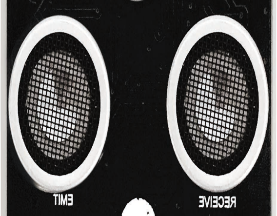
The ultrasonic sensor is shaped like two eyes, of which one serves as the transmitting end and the other the receiving end.
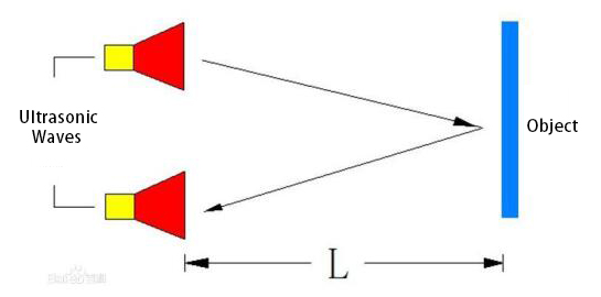
It detects the time (t) gap between emitting signals and receiving them. And the propagation speed of sound in the air is about 343m/s, and distance = speed * time. However, the ultrasonic wave emits and comes back, which is 2 times of distance. Therefore, it needs to be divided by 2, the distance measured by ultrasonic wave = (speed * time)/2.
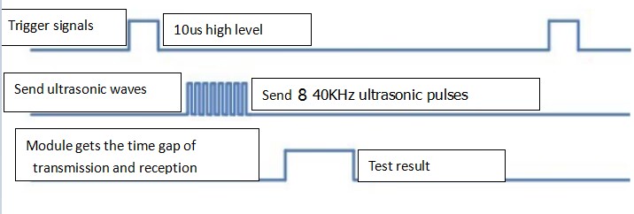
Usage and timing chart of ultrasonic module:
Setting the delay time of Trig pin of SR04 to 10μs at least, which can trigger it to detect distance.
After triggering, the module will automatically send eight 40KHz ultrasonic pulses and detect whether there is a signal return. This step will be completed automatically by the module.
If the signal returns, the Echo pin will output a high level, and the duration of the high level is the time from the transmission of the ultrasonic wave to the return.
|
|---|
Parameters:
Power supply: +5V DC
Quiescent current: <2mA
Working current: 15mA
Effective angle: <15°
Measuring distance: 2 cm to 40 cm
Resolution: 0.3 cm
Measuring angle: 30 degrees
Trigger input pulse width: 10uS
Preparations
A.Turn the Bluetooth dial switch to OFF .
B.Connect the yellow car and the computer via a USB cable.
C.Compile and upload the test code through Arduino IDE.
Test Code:
/*
kidsbits coding robot kit
Project 4
Distance Detector
http//www.kidsbits.cc
*/
volatile int distance;        //Define a variable distance

float checkdistance_2_3() {     //Define a range function
//The sensor is triggered by a high pulse of 10 microseconds or more.
  digitalWrite(2, LOW);       //Give a short low pulse in advance to ensure a clean high pulse:
  delayMicroseconds(2);       //Delay 2 microseconds
  digitalWrite(2, HIGH);
  delayMicroseconds(10);      //Delay 10 microseconds
  digitalWrite(2, LOW);
  float distance = pulseIn(3, HIGH) / 58.00;      //Distance calculation formula
  delay(10);
  return distance;
}

void setup(){
  Serial.begin(9600);
  distance = 0;
  pinMode(2, OUTPUT);
  pinMode(3, INPUT);
  pinMode(6, OUTPUT);
  pinMode(7, OUTPUT);
}

void loop(){
  distance = checkdistance_2_3();
  delay(1);
  Serial.println(distance);              //Serial monitor displays distance
  if (distance > 0 && distance < 8) {       //If the distance is greater than 0 and less than 8cm
    tone(6,532);
    tone(7,532);
    delay(250);
    noTone(6);
    noTone(7);
    delay(250);
    tone(6,532);
    tone(7,532);
    delay(250);
    noTone(6);
    noTone(7);
    delay(1000);

  }

}
Test Results:
Upload the above test code, the yellow robot will emit“tick,tick”when detecting the obstacle away from 0cm to 8cm.
Project 5: Button Counter
Description:
In daily life, we usually need to count numbers. In this project, we will make a button counter.
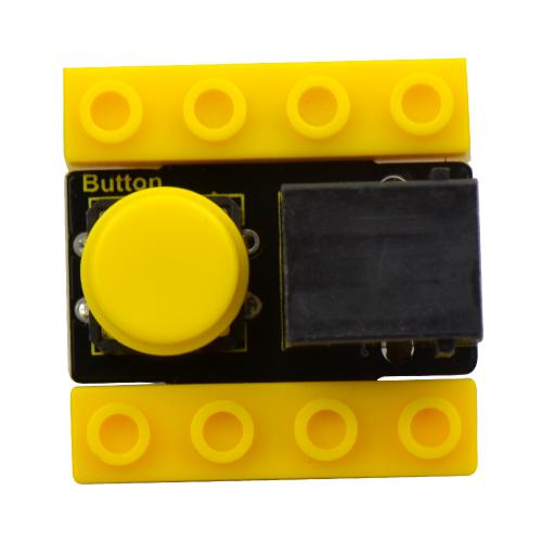
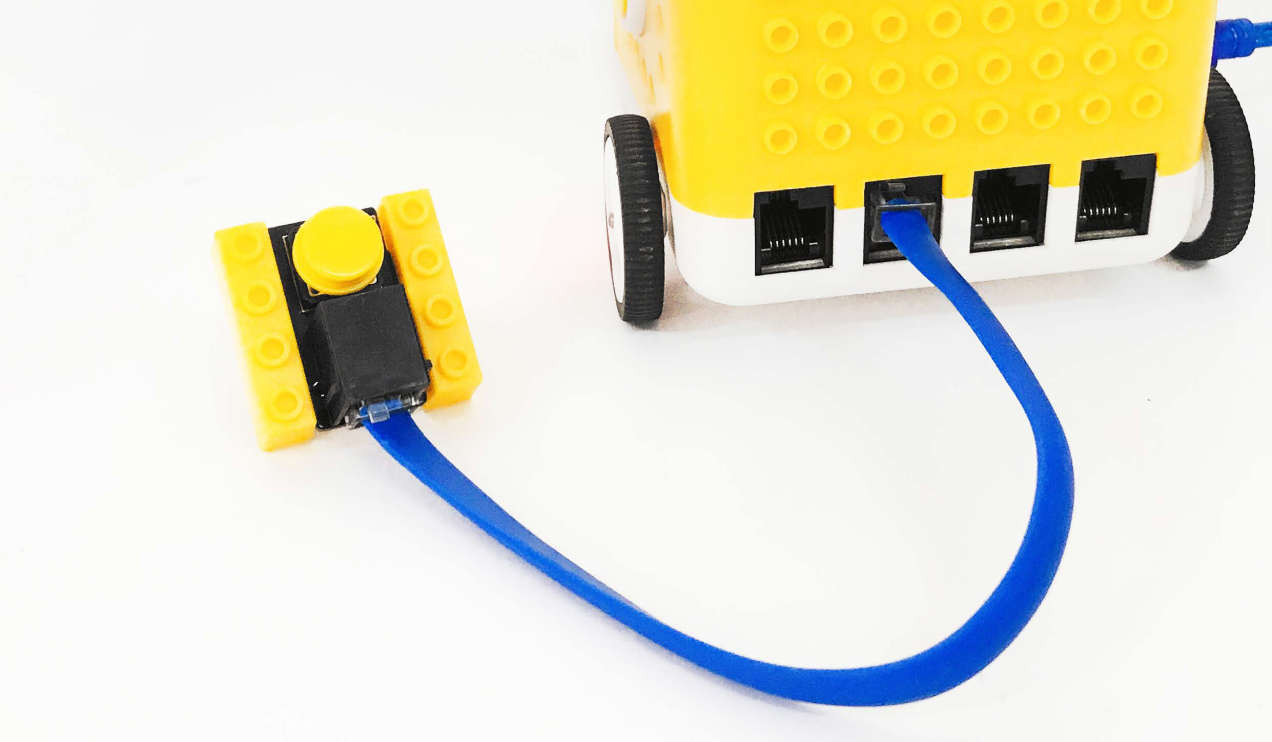
Button Module:
This button module integrates the LEGO building block and Easy Plug port, which can be fixed on the yellow robot flexibly. Only a blue cable needed can interface it with the yellow robot. You are free from worries over reversely wire up or damaging the module
When we press it, low level signals will be output; when it is released, high level signals will be output
Parameter
Interface: EASY plug
Working voltage: DC 5V
Output signal: digital signal
Connection Diagram:
Use the blue cable to connect the button module to D12 port of the yellow robot
Preparation
Slide the BT switch to OFF end
Connect the yellow robot to the computer by a USB cable
Connect the button module to D12 through a blue cable
Upload test code on Arduino IDE
Test Code:
/*
kidsbits coding robot kit
Project 5
Button Counter
http//www.kidsbits.cc
*/
volatile int num;      //Define the integer variable num

void setup(){
  num = 0;              //variable num is 0
  Serial.begin(9600);        //Set baud rate
  pinMode(12, INPUT);      //Set digital port 12 to input
}

void loop(){
  if (digitalRead(12) == 0) {     //Judge whether digital port 12 is low level
    delay(10);                  //Delay 10ms eliminate button jitter
    if (digitalRead(12) == 0) {
      delay(200);
      if (digitalRead(12) == 1) {    //Judge whether digital port 12 is high level
        delay(10);                  //Delay 10ms eliminate button jitter
        if (digitalRead(12) == 1) {
          num = num + 1;     //Count the number of times the key is pressed
          Serial.println(num);   //Display the number of times the key is pressed

        }
      }
    }
  }
}
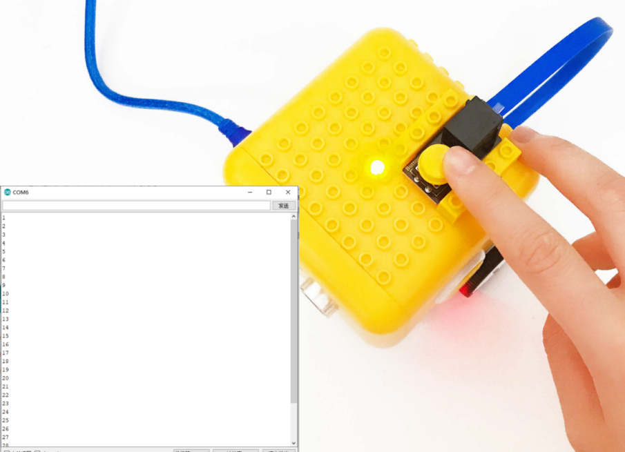
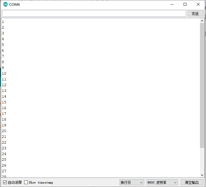
Test Result:
Upload code to the yellow robot, open serial monitor and press the button. You will see the data as follows:
Code Explanation:
When you press or release button, different digital signals will be output due to the shaking of the button. To eliminate shaking, we need to delay time. In this chapter, we delay in 10ms
Project 6: Motor
Introduction:
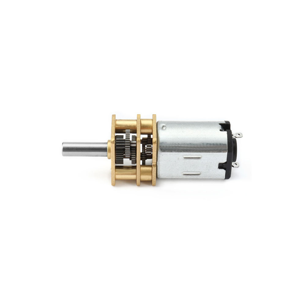
DC reduction motor, also called gear reduction motor, is developed on the ordinary DC motor. It has a matching gear reduction box which provides a lower speed but a larger torque. Furthermore, different reduction ratios of the box can provide different speeds and torques.
Parameters:
Rated voltage: 6.0V DC
Operating voltage: 1.0V ~ 6.0V DC
Rated load: torque plate load 0.5kg-cm
Rotation direction: clockwise or counterclockwise when viewed from the shaft extension
Motor posture: all directions of output shaft
Operating temperature: -10℃~+60℃
Storage temperature: -20℃~+85℃
Description of chip:
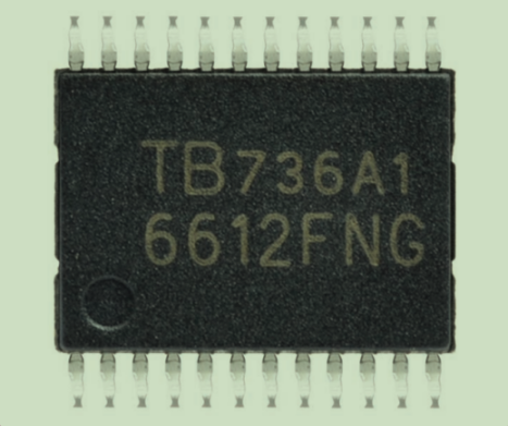
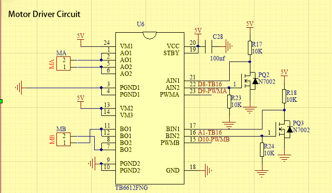
A motor driver is a chip integrated with CMOS control circuit and power DMOS device. It can be used to form a complete motion control system with the main processor, motor and incremental encoder. It can be applied to drive inductive loads such as DC motors, stepping motors and relays. What’s more, it can control the DC reduction motor to rotate clockwise or anticlockwise.
The yellow car introduced in this course uses the TB6612FNG motor drive chip, which is a device driving DC motors. Compared with the traditional L298N, the module has a much higher efficiency and a significant reduction in size. Within the rated range, the chip basically does not generate heat.
It has a high-current MOSFET-H bridge structure and dual-channel circuit output so it can drive 2 motors at the same time. TB6612FNG can output continuous drive current up to 1.2 A per channel, and it boasts four motor control modes: rotate clockwise, rotate anticlockwise, brake and stop.
Working Principle
The DC reduction motor on the left side of the yellow car has two pins which are connected to the digital pin 8 and pin 9 (a PMW pin)controlling the rotation direction and the speed respectively.(This PMW pin can not only output high and low level stably but make constant changes in high and low levels within a given time so as to control the speed of the motor. It can output values from 0-255 of which 255 represents high level while 0 implies low level.)
Its Left Wheel |
||
|---|---|---|
Digital Pin 8 |
Digital Pin 9(PWM) |
DC Reduction Motor |
Low Level |
0 |
Stop |
Low Level |
200 |
Rotate anticlockwise |
High Level |
200 |
Rotate clockwise |
High Level |
0 |
Stop |
The DC reduction motor on the right side of the car also has two pins, one of which is connected to the analog pin A1 (also the digital pin 15) to control directions and the other is linked with digital pin 10 to adjust speed. Please note that analog pins can function like digital pins while digital pins can not be taken as analog ones.
Its Right Wheel |
||
|---|---|---|
Digital Pin A1 |
Digital Pin 10(PWM) |
DC Reduction Motor |
Low Level |
0 |
Stop |
Low Level |
200 |
Rotate clockwise |
High Level |
200 |
Rotate anticlockwise |
High Level |
0 |
Stop |
Test Code:
/*
kidsbits coding robot kit
Project 6
Motor
http//www.kidsbits.cc
*/
void setup(){
  pinMode(8, OUTPUT);
  pinMode(A1, OUTPUT);
}

void loop(){
//advance
  digitalWrite(8,LOW);
  digitalWrite(A1,LOW);
  analogWrite(9,200);
  analogWrite(10,200);
  delay(3000);
  //move back
  digitalWrite(8,HIGH);
  digitalWrite(A1,HIGH);
  analogWrite(9,194);
  analogWrite(10,200);
  delay(3000);
//  stop
  digitalWrite(8,HIGH);
  digitalWrite(A1,HIGH);
  analogWrite(9,0);
  analogWrite(10,0);
  delay(3000);
//turn left
  digitalWrite(8,HIGH);
  digitalWrite(A1,LOW);
  analogWrite(9,120);
  analogWrite(10,120);
  delay(2000);
  //turn right
  digitalWrite(8,LOW);
  digitalWrite(A1,HIGH);
  analogWrite(9,120);
  analogWrite(10,120);
  delay(2000);
}
Test Results:
The car will move forward in 3s, then go backwards in 3s, stop in 3s, and turn left in 3s and then right in 3s and repeat this pattern.
Code Explanation:
digitalWrite(8,LOW); The control of directions (move anticlockwise or clockwise)is realized by the changes in high and low levels and digital pins are enough for this to happen.
analogWrite(9,200);The adjustment of speed is realized by PMW and it relies on the PMW pin of Arduino to make this possible.
Extension Project:
Now,let’s control the speed of the motor by PMW.
void setup(){

pinMode(8, OUTPUT);

pinMode(A1, OUTPUT);

}

void loop(){

//Move forward

digitalWrite(8,LOW);

digitalWrite(A1,LOW);

analogWrite(9,200);

analogWrite(10,200);

delay(3000);

//Move backwards

digitalWrite(8,HIGH);

digitalWrite(A1,HIGH);

analogWrite(9,194);

analogWrite(10,200);

delay(3000);

//Stop

digitalWrite(8,HIGH);

digitalWrite(A1,HIGH);

analogWrite(9,0);

analogWrite(10,0);

delay(3000);

//Turn left

digitalWrite(8,HIGH);

digitalWrite(A1,LOW);

analogWrite(9,120);

analogWrite(10,120);

delay(2000);

//Turn right

digitalWrite(8,LOW);

digitalWrite(A1,HIGH);

analogWrite(9,120);

analogWrite(10,120);

delay(2000);

}
//***********************************************************************
The motor will slow down when the code is uploaded.
Project 7: 8*8 Dot Matrix Dispaly

Description:
We add an LED panel displaying numerous pictures to a robot. In fact, this panel is called 8*8 dot matrix display. It comes with 64 LEDs, of which can be lit separately or together. Different lit areas can foster distinct pictures
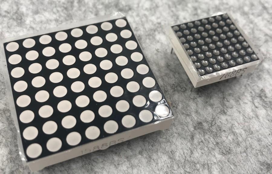 8*8 Dot Matrix
Composed of LED emitting tube diodes, LED dot matrix are applied widely to public information display like advertisement screen and bulletin board, by controlling LED to show words, pictures and videos, etc.
Divided into single-color, double-color, and three-color lights according to emitting color , LED dot matrix could show red, yellow, green and even true color.
There are different types of matrices, including 4×4, 8×8 and 16×16 and etc.
The 8×8 dot matrix contains 64 LEDs.
The inner structure of 8×8 dot matrix is shown below.
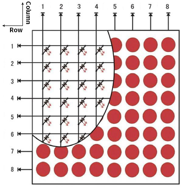
Every LED is installed on the cross point of row line and column line. When the voltage on a row line increases, and the voltage on the column line reduces, the LED on the cross point will light up. 8×8 dot matrix has 16 pins. Put the silk-screened side down and the numbers are 1,8, 9 and 16 in anticlockwise order as marked below.
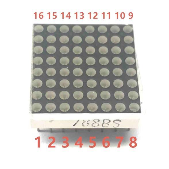
The definition inner pins are shown below:
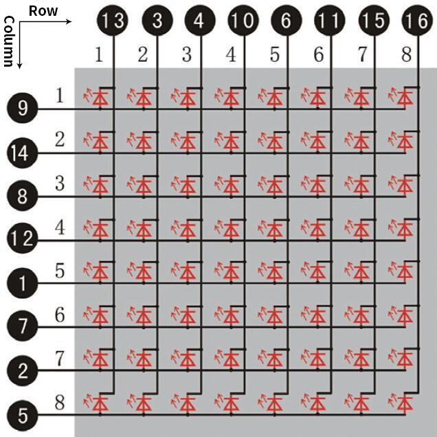
For instance, to light up the LED on row 1 and column 1, you should increase the voltage of pin 9 and reduce the voltage of pin 13.
HT16K33 8X8 Dot Matrix
The HT16K33 is a memory mapping and multi-purpose LED controller driver. The max. Display segment numbers in the device is 128 patterns (16 segments and 8 commons) with a 13*3 (MAX.) matrix key scan circuit. The software configuration features of the HT16K33 makes it suitable for multiple LED applications including LED modules and display subsystems. The HT16K33 is compatible with most microcontrollers and communicates via a two-line bidirectional I2C-bus.
The picture below is the working schematic of HT16K33 chip
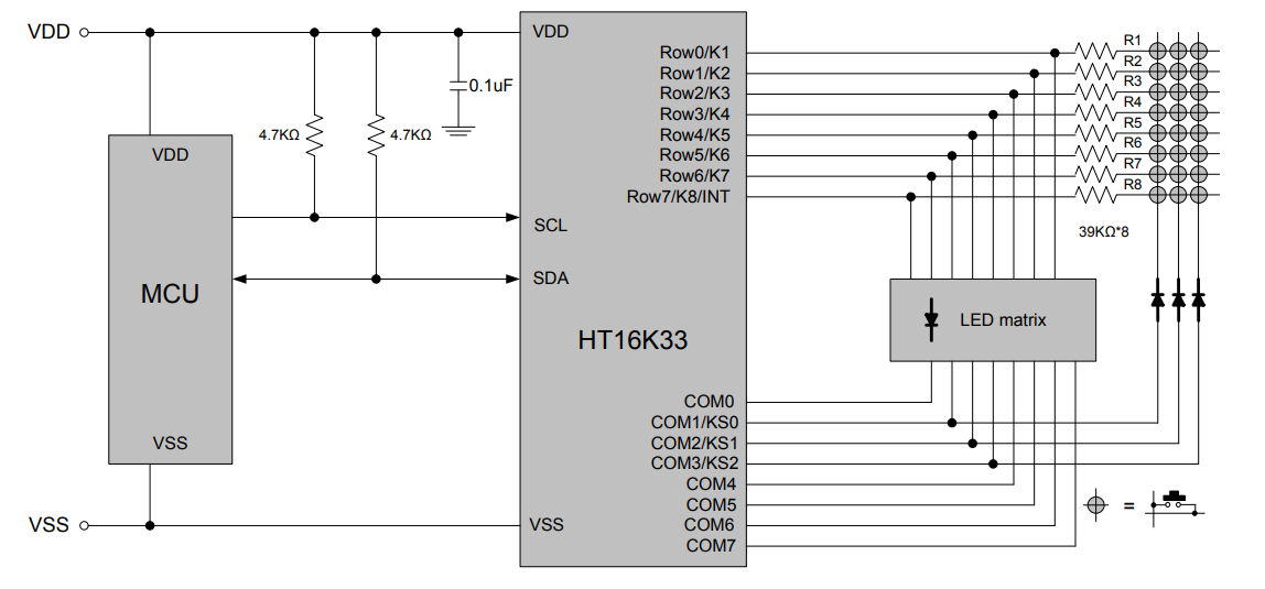
We design the drive module of 8*8 dot matrix based on the above principle. We could control the dot matrix by I2C communication and two pins of microcontroller, according to the above diagram.
Specification of 8*8 dot matrix
Input voltage: 5V
Rated input frequency: 400KHZ
Input power: 2.5W
Input current: 500mA
4. Introduction for Modulus Tool
The online version of dot matrix modulus tool:
① Open the link to enter the following page.
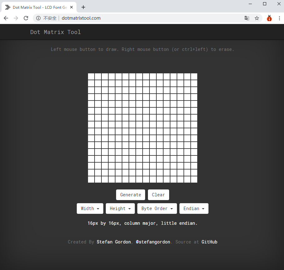
② The dot matrix is 8*8 in this project, so set the height to 8, width to 8, as shown below.
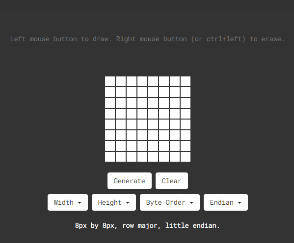
Click Byte order to select“Row major”
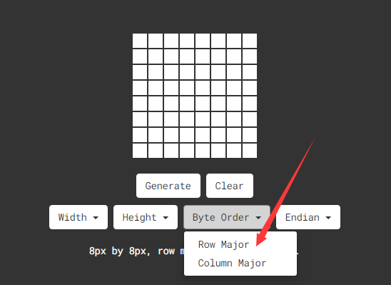
③ Generate hexadecimal data from the pattern
As shown below, the left button of the mouse is for selection while the right is for canceling. Thus you could use them to draw the pattern you want, then click Generate, to yield the hexadecimal data needed.
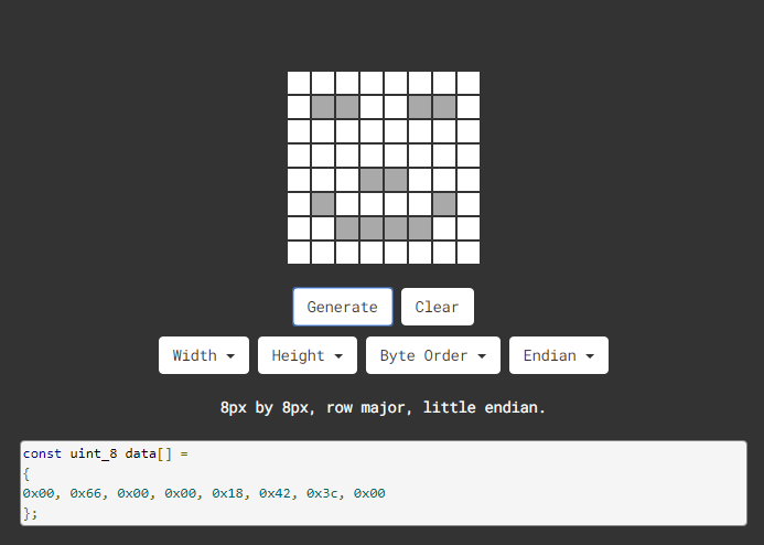
The generated hexadecimal code(0x00, 0x66, 0x00, 0x00, 0x18, 0x42, 0x3c, 0x00) is what will be displayed, so you need to save it for next procedure.
Preparation
Slide the BT switch to OFF end
Connect the yellow robot to the computer by a USB cableUpload test code on Arduino IDE
Test Code:
Code 1:
/*
kidsbits coding robot kit
Project 7-1
8*8 Dot Matrix Dispaly
http//www.kidsbits.cc
*/
#include <Matrix.h>

Matrix myMatrix(A4,A5);     //Instantiate an object myMatrix, and define the communication pins


void setup(){
  myMatrix.begin(0x70);     //communication address
}

void loop(){
  myMatrix.clear();     //clear
  myMatrix.drawStr("hello!");

}
Upload the above code, the yellow robot shows“hello!”
Code 2:
/*
kidsbits coding robot kit
Project 7-2
8*8 Dot Matrix Dispaly
http//www.kidsbits.cc
*/
#include <Matrix.h>

Matrix myMatrix(A4,A5);         //Instantiate an object myMatrix, and define the communication pins
uint8_t LedArray1[8]={0xff,0x81,0xbd,0xa5,0xa5,0xbd,0x81,0xff};     //Define an array and assign it to the array data obtained by the modulating tool
uint8_t  LEDArray[8];   //Define an array variable without an initial value to facilitate the processing of multiple emoticon arrays

void setup(){
  myMatrix.begin(0x70);   //communication address

}

void loop(){
  myMatrix.clear();           //clear
  for(int i=0; i<8; i++)      //The array has 8 pieces of data, which are looped 8 times, analyzed one by one
  {
    LEDArray[i]=LedArray1[i];   //Assign the emoticon array data to LEDArray one by one
    for(int j=7; j>=0; j--)    //Each data has 8 bits, so it needs to be looped 8 times
    {
      if((LEDArray[i]&0x01)>0)  //Check whether the last bit of the data is >0, that is, whether it is 1
      myMatrix.drawPixel(j, i,1); //Light up the corresponding point
      LEDArray[i] = LEDArray[i]>>1; //LEDArray[i] moves one bit to the right to judge the first 1 bit
    }
  }
  myMatrix.writeDisplay();       //dot matrix display

}
Upload the above code, the yellow robot displays a concentric square,
Code 3:
/*
kidsbits coding robot kit
Project 7-3
8*8 Dot Matrix Dispaly
http//www.kidsbits.cc
*/
#include <Matrix.h>

Matrix myMatrix(A4,A5);       //Instantiate an object myMatrix, and define the communication pins
//Define an array and assign it to the array data obtained by the modulating tool
uint8_t LedArray1[8]={0x18,0x18,0x18,0x18,0x99,0x5a,0x3c,0x18};
uint8_t  LEDArray[8];     //Define an array and assign it to the array data obtained by the modulating tool
uint8_t LedArray2[8]={0x10,0x20,0x40,0xff,0xff,0x40,0x20,0x10};
uint8_t LedArray3[8]={0x18,0x3c,0x5a,0x99,0x18,0x18,0x18,0x18};
uint8_t LedArray4[8]={0x08,0x04,0x02,0xff,0xff,0x02,0x04,0x08};
uint8_t LedArray5[8]={0x00,0x18,0x24,0x00,0x00,0xa5,0xa5,0x42};

void setup(){
  myMatrix.begin(0x70);  //communication address

}

void loop(){
  myMatrix.clear();       //clear
  for(int i=0; i<8; i++)     //The array has 8 pieces of data, which are looped 8 times, analyzed one by one
  {
    LEDArray[i]=LedArray1[i];   //Assign the emoticon array data to LEDArray one by one
    for(int j=7; j>=0; j--)       //Each data has 8 bits, so it needs to be looped 8 times
    {
      if((LEDArray[i]&0x01)>0)    //Check whether the last bit of the data is >0, that is, whether it is 1
      myMatrix.drawPixel(j, i,1);     //Light up the corresponding point
      LEDArray[i] = LEDArray[i]>>1;   //LEDArray[i] moves one bit to the right to judge the first 1 bit
    }
  }
  myMatrix.writeDisplay();    //dot matrix display
  delay(1000);
  myMatrix.clear();
  myMatrix.writeDisplay();
  for(int i=0; i<8; i++)
  {
    LEDArray[i]=LedArray2[i];
    for(int j=7; j>=0; j--)
    {
      if((LEDArray[i]&0x01)>0)
      myMatrix.drawPixel(j, i,1);
      LEDArray[i] = LEDArray[i]>>1;
    }
  }
  myMatrix.writeDisplay();
  delay(1000);
  myMatrix.clear();
  myMatrix.writeDisplay();
  for(int i=0; i<8; i++)
  {
    LEDArray[i]=LedArray3[i];
    for(int j=7; j>=0; j--)
    {
      if((LEDArray[i]&0x01)>0)
      myMatrix.drawPixel(j, i,1);
      LEDArray[i] = LEDArray[i]>>1;
    }
  }
  myMatrix.writeDisplay();
  delay(1000);
  myMatrix.clear();
  myMatrix.writeDisplay();
  for(int i=0; i<8; i++)
  {
    LEDArray[i]=LedArray4[i];
    for(int j=7; j>=0; j--)
    {
      if((LEDArray[i]&0x01)>0)
      myMatrix.drawPixel(j, i,1);
      LEDArray[i] = LEDArray[i]>>1;
    }
  }
  myMatrix.writeDisplay();
  delay(1000);
  myMatrix.clear();
  myMatrix.writeDisplay();
  for(int i=0; i<8; i++)
  {
    LEDArray[i]=LedArray5[i];
    for(int j=7; j>=0; j--)
    {
      if((LEDArray[i]&0x01)>0)
      myMatrix.drawPixel(j, i,1);
      LEDArray[i] = LEDArray[i]>>1;
    }
  }
  myMatrix.writeDisplay();
  delay(1000);
  myMatrix.clear();
  myMatrix.writeDisplay();

}
Upload code, the yellow robot will show arrow up,down, leftward and rightward and smile image, circularly.
Project 8: Obstacle Avoidance Robot
Description:
We have learned about distance detection and motor drive. In this lesson, we combine them together. In fact, we only need to change a test code to convert the car into an obstacle avoidance car.
detection |
Distance away from the left obstacle |
Distance1(unit:cm) |
|---|---|---|
Distance away from the right obstacle |
Distance2(unit:cm) |
|
Distance away from the front obstacle |
distance(unit:cm) |
|
Condition |
Status |
|
0<distance<15 |
Distance1> distance2 |
Turn left |
Distance1<=distance2 |
Turn right |
|
distance>=15 |
Go forward |
Preparation
Slide the BT switch to OFF end
Connect the yellow robot to the computer by a USB cable
Upload test code on Arduino IDE
Test Code:
Pin Trig (trigger signal input) and pin Echo are connected to digital 2 and 3 of the yellow robot.
/*
kidsbits coding robot kit
Project 8
Obstacle Avoidance Robot
http//www.kidsbits.cc
*/
volatile int distance;
volatile int distance1;
volatile int distance2;
void Stop() {          //Stop
  digitalWrite(8,HIGH);
  pinMode(A1, OUTPUT);
  digitalWrite(A1,HIGH);
  analogWrite(9,0);
  analogWrite(10,0);
}

void left() {         //turn left
  digitalWrite(8,HIGH);
  pinMode(A1, OUTPUT);
  digitalWrite(A1,LOW);
  analogWrite(9,120);
  analogWrite(10,120);
}

float checkdistance_2_3() {         //Ultrasonic ranging code
  digitalWrite(2, LOW);          //Define pin 2 output low level
  delayMicroseconds(2);         //Delay 2 ms
  digitalWrite(2, HIGH);        //Define pin 2 output high level
  delayMicroseconds(10);      //Delay 10 ms
  digitalWrite(2, LOW);
  float distance = pulseIn(3, HIGH) / 58.00;     // calculate distance
  delay(10);
  return distance;
}

void back() {           //move back
  digitalWrite(8,HIGH);
  pinMode(A1, OUTPUT);
  digitalWrite(A1,HIGH);
  analogWrite(9,150);
  analogWrite(10,150);
}

void buzzer() {        //Buzzer code
  tone(6,532);
  tone(7,532);
  delay(250);
  noTone(6);
  noTone(7);
  delay(250);
  tone(6,532);
  tone(7,532);
  delay(250);
  noTone(6);
  noTone(7);
  delay(1000);
}

void front() {           //advance
  digitalWrite(8,LOW);
  pinMode(A1, OUTPUT);
  digitalWrite(A1,LOW);
  analogWrite(9,150);
  analogWrite(10,150);
}

void right() {         //turn right
  digitalWrite(8,LOW);
  pinMode(A1, OUTPUT);
  digitalWrite(A1,HIGH);
  analogWrite(9,120);
  analogWrite(10,120);
}

void setup(){
  Serial.begin(9600);
  distance = 0;
  distance1 = 0;
  distance2 = 0;
  pinMode(8, OUTPUT);
  pinMode(2, OUTPUT);
  pinMode(3, INPUT);
  pinMode(6, OUTPUT);
  pinMode(7, OUTPUT);
}

void loop(){
  distance = checkdistance_2_3();     //Assign the distance value to distance
  if (distance < 15&&distance > 0) {         //Judge whether the distance is less than 15cm
    Stop();
    buzzer();
    delay(1000);
    left();
    delay(380);
    Stop();
    distance1 = checkdistance_2_3();
    delay(1000);
    right();
    delay(750);
    Stop();
    distance2 = checkdistance_2_3();
    delay(1000);
    if (distance1 > distance2) {      //If the left is greater than the right
      left();
      delay(750);
      front();

    } else {
      front();

    }

  } else {
    front();

  }

}
Test Result:
If the obstacle distance is more than and equal to 15cm, the car will go forward. If less than 15cm, the car will stop and play “tick,tick”
sound. If the left obstacle distance is greater than the right distance, the car will turn left. On the contrary, it will turn right.
Project 9: Line Tracking Smart Car
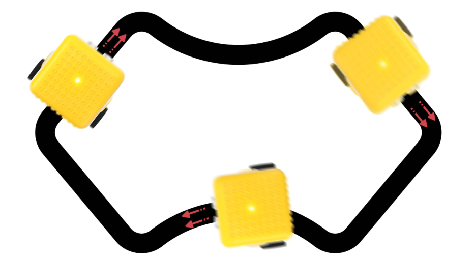
Description
The previous projects are inclusive of the knowledge of multiple sensors and modules. Next, we will work on a little challenging task.
Based on the working principle of the line tracking sensor we could make a line tracking car.
The tracking sensor is actually an infrared sensor. Its working principle is to convert the intensity of the reflected signal into a current signal. During the detection process, black color is active at high level and white is active at low level. Its detection height is 0- 1cm. In the project, we detect the status of the tracking sensor, then analyze and compare the data obtained, and then control the rotation of the two sets of motors according to certain logic, so as to control the yellow robot.
Flow Chart:
Detection |
Left tracking sensor |
detects black line:LOW |
|---|---|---|
detects white line:HIGH |
||
Right tracking sensor |
detects black line:LOW |
|
detects white line:HIGH |
||
Condition |
Status |
|
Two sensors detect black line |
Go forward |
|
Left sensor detects white line and right one detects the black line |
Turn right (set PWM to 100) |
|
left sensor detects the black line and the right one detects white line |
Turn left (set PWM to100) |
|
Two sensors don’t black line |
Stop |
Preparation
Slide the BT switch to OFF end
Connect the yellow robot to the computer by a USB cable(3)Upload test code on Arduino IDE
Test Code:
/*
kidsbits coding robot kit
Project 9
Line Tracking robot
http//www.kidsbits.cc
*/
#include <Matrix.h>

Matrix myMatrix(A4,A5);        //Instantiate an object myMatrix, and define the communication pins
uint8_t LedArray1[8]={0xff,0x81,0xbd,0xa5,0xa5,0xbd,0x81,0xff};   //Define an array and assign it to the array data obtained by the modulating tool
uint8_t  LEDArray[8];
void left() {              //Define the state of the left turn
  digitalWrite(8,HIGH);    //Left motor rotates anticlockwise
  digitalWrite(A1,LOW);   //right motor rotates clockwise
  analogWrite(9,100);   //Left motor speed is 100
  analogWrite(10,100);    //right motor speed is 100
}

void Stop() {           //Define the state of stop
  digitalWrite(8,HIGH);   //Left motor rotates anticlockwise
  digitalWrite(A1,HIGH);    //right motor rotates anticlockwise
  analogWrite(9,0);     //Left motor speed is 0
  analogWrite(10,0);      //right motor speed is 0

void right() {          //Define the state of the right turn
  digitalWrite(8,LOW);      //Left motor rotates clockwise
  digitalWrite(A1,HIGH);      //right motor rotates anticlockwise
  analogWrite(9,102);     //Left motor speed is 102
  analogWrite(10,102);      //right motor speed is 102
}

void front() {            //Define the state of advance
  digitalWrite(8,LOW);      //Left motor rotates clockwise
  digitalWrite(A1,LOW);       //right motor rotates clockwise
  analogWrite(9,150);     //Left motor speed is 150
  analogWrite(10,150);      //right motor speed is 150
}

void setup(){
  Serial.begin(9600);
  myMatrix.begin(0x70);
  myMatrix.clear();   //clear
  delay(1000);        // delay
  for(int i=0; i<8; i++)
  {
    LEDArray[i]=LedArray1[i];
    for(int j=7; j>=0; j--)
    {
      if((LEDArray[i]&0x01)>0)
      myMatrix.drawPixel(j, i,1);
      LEDArray[i] = LEDArray[i]>>1;
    }
  }
  myMatrix.writeDisplay();
  pinMode(8, OUTPUT);
  pinMode(4, INPUT);
  pinMode(5, INPUT);
  pinMode(A1, OUTPUT);
}

void loop(){
  Serial.println(digitalRead(4));
  Serial.println(digitalRead(5));
  if (digitalRead(4) == 0 && digitalRead(5) == 1) {
    left();

  } else if (digitalRead(4) == 1 && digitalRead(5) == 0) {
    right();
  } else if (digitalRead(4) == 1 && digitalRead(5) == 1) {
    Stop();
  } else {
    front();

  }
}
(4) Test Result:
Upload the code, slide the switch to ON end. Then the yellow robot will follow the black line.
Project 10: Magical Pattern
Description:
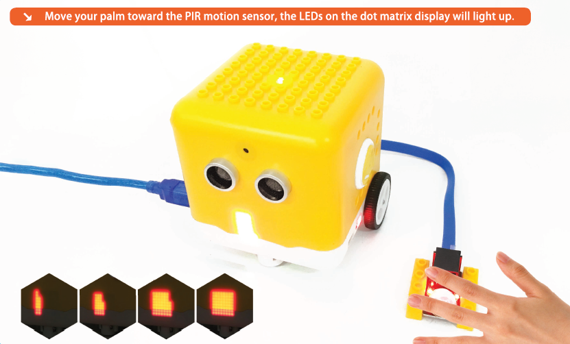
We’ve introduced how to use the LED dot matrix and change pictures. In this project, we will make dot matrix show different images through a PIR motion sensor.
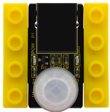
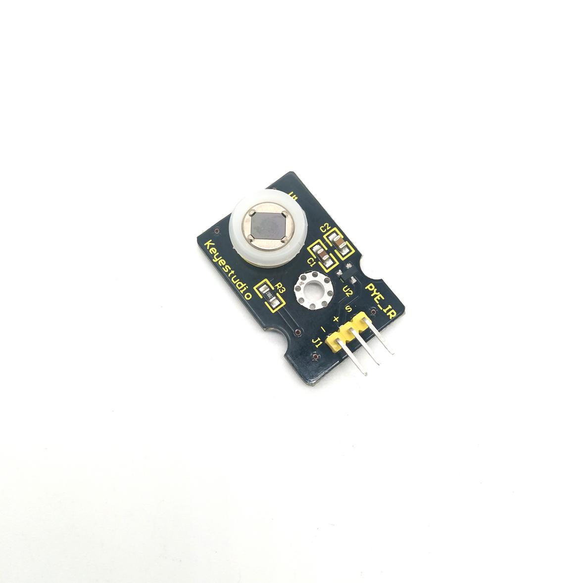
PIR Motion Sensor:
This PIR motion sensor integrates the LEGO building block and Easy Plug port, which can be fixed on the yellow robot flexibly. Only a blue cable needed can interface it with the yellow robot. You are free from worries over reversely wire up or damaging the module.
It can detect infrared signals of people or animals in motion, and output switch signals. It also is highly sensitive and reliable with ultra-low power consumption and ultra-low voltage working mode.
Additionally it can be applied to various automatic induction electrical equipment, especially automatic control products powered by dry batteries.
Parameter
Interface: EASY plug
Working voltage: DC 3.3V~5V
Working current: 15 uA
Output signal: digital signal
Output delay time (high level): about 2.3 ~ 3 seconds
Detection range: 0~50cm
Detection angle: 100º.
Special note:
1. When testing, first open the white lens, you can see the rectangular sensing part. When the long line of the rectangular sensing part is parallel to the ground, the distance is the best.
2. When testing, the sensor needs to be covered with white lens, otherwise it will affect the distance.
3. The distance is best at 25℃, and the detection distance is shortened when it exceeds 30℃.
 4. Done powering up and
uploading the code, you need to wait 5-10 seconds then start testing, otherwise
it is not sensitive.
4. Done powering up and
uploading the code, you need to wait 5-10 seconds then start testing, otherwise
it is not sensitive.
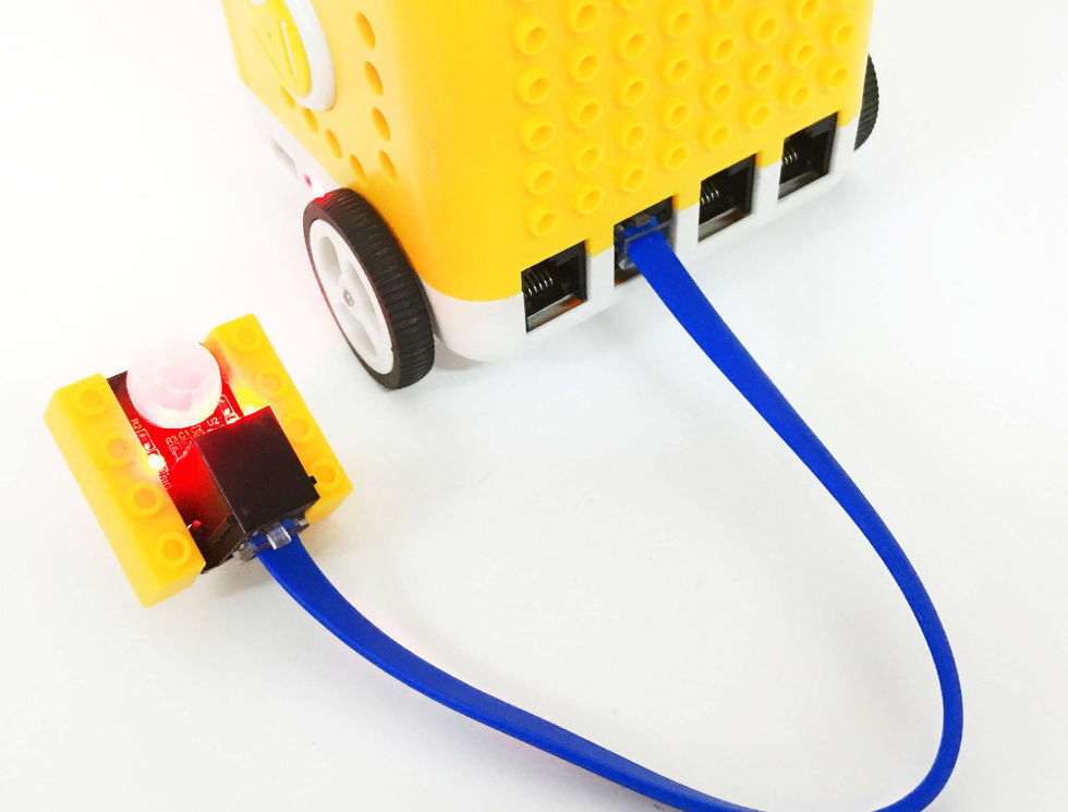
Connection Diagram:
Connect the PIR motion sensor to D12 of the yellow robot
Preparation
Slide the BT switch to OFF end
Connect the yellow robot to the computer by a USB cable
Connect the PIR motion sensor to D12 of the yellow robot
Upload test code on Arduino IDE
Test Code:
/*
kidsbits coding robot kit
Project 10
Magical Pattern
http//www.kidsbits.cc
*/
#include <Matrix.h>

Matrix myMatrix(A4,A5);           //Instantiate an object myMatrix, and define the communication pins
uint8_t LedArray1[8]={0xff,0x81,0x81,0x81,0x81,0x81,0x81,0xff};
uint8_t  LEDArray[8];  //Define an array variable without an initial value to facilitate the processing of multiple emoticon arrays
uint8_t LedArray2[8]={0x00,0x7e,0x42,0x42,0x42,0x42,0x7e,0x00};
uint8_t LedArray3[8]={0x00,0x00,0x3c,0x24,0x24,0x3c,0x00,0x00};
uint8_t LedArray4[8]={0x00,0x00,0x00,0x18,0x18,0x00,0x00,0x00};
uint8_t LedArray5[8]={0x00,0x00,0x3c,0x24,0x24,0x3c,0x00,0x00};
uint8_t LedArray6[8]={0x00,0x7e,0x42,0x42,0x42,0x42,0x7e,0x00};
uint8_t LedArray7[8]={0xff,0x81,0x81,0x81,0x81,0x81,0x81,0xff};
//The pattern on the dot matrix displays that the large square gradually decreases from the tool


void setup(){
  Serial.begin(9600);
  myMatrix.begin(0x70);   //communication address

  myMatrix.clear();     //clear
  pinMode(12, INPUT);
}

void loop(){
  Serial.println(digitalRead(12));
  if (digitalRead(12) == 1) {       //If the PIR motion sensor senses someone nearby
    myMatrix.clear();
    myMatrix.writeDisplay();      //dot matrix display
    for (int i = 0; i <= 8; i = i + (1)) {    //The array has 8 pieces of data, which are looped 8 times, analyzed one by one
      for (int j = 0; j <= 8; j = j + (1)) {
        myMatrix.drawPixel(i-1,j-1,1);   //Light up the corresponding point
        myMatrix.writeDisplay();  //dot matrix display
        delay(100);
      }
    }

  } else {        //else
    for(int i=0; i<8; i++)
    {
      LEDArray[i]=LedArray1[i];   //Assign the emoticon array data to LEDArray one by one
      for(int j=7; j>=0; j--)      //Each data has 8 bits, so it needs to be looped 8 times
      {
        if((LEDArray[i]&0x01)>0)   //Check whether the last bit of the data is >0, that is, whether it is 1
        myMatrix.drawPixel(j, i,1);    //Light up the corresponding point
        LEDArray[i] = LEDArray[i]>>1;   //LEDArray[i] moves one bit to the right to judge the first 1 bit
      }
    }
    myMatrix.writeDisplay();
    delay(200);
    myMatrix.clear();
    myMatrix.writeDisplay();
    for(int i=0; i<8; i++)
    {
      LEDArray[i]=LedArray2[i];
      for(int j=7; j>=0; j--)
      {
        if((LEDArray[i]&0x01)>0)
        myMatrix.drawPixel(j, i,1);
        LEDArray[i] = LEDArray[i]>>1;
      }
    }
    myMatrix.writeDisplay();
    delay(200);
    myMatrix.clear();
    myMatrix.writeDisplay();
    for(int i=0; i<8; i++)
    {
      LEDArray[i]=LedArray3[i];
      for(int j=7; j>=0; j--)
      {
        if((LEDArray[i]&0x01)>0)
        myMatrix.drawPixel(j, i,1);
        LEDArray[i] = LEDArray[i]>>1;
      }
    }
    myMatrix.writeDisplay();
    delay(200);
    myMatrix.clear();
    myMatrix.writeDisplay();
    for(int i=0; i<8; i++)
    {
      LEDArray[i]=LedArray4[i];
      for(int j=7; j>=0; j--)
      {
        if((LEDArray[i]&0x01)>0)
        myMatrix.drawPixel(j, i,1);
        LEDArray[i] = LEDArray[i]>>1;
      }
    }
    myMatrix.writeDisplay();
    delay(200);
    myMatrix.clear();
    myMatrix.writeDisplay();
    for(int i=0; i<8; i++)
    {
      LEDArray[i]=LedArray5[i];
      for(int j=7; j>=0; j--)
      {
        if((LEDArray[i]&0x01)>0)
        myMatrix.drawPixel(j, i,1);
        LEDArray[i] = LEDArray[i]>>1;
      }
    }
    myMatrix.writeDisplay();
    delay(200);
    myMatrix.clear();
    myMatrix.writeDisplay();
    for(int i=0; i<8; i++)
    {
      LEDArray[i]=LedArray6[i];
      for(int j=7; j>=0; j--)
      {
        if((LEDArray[i]&0x01)>0)
        myMatrix.drawPixel(j, i,1);
        LEDArray[i] = LEDArray[i]>>1;
      }
    }
    myMatrix.writeDisplay();
    delay(200);
    myMatrix.clear();
    myMatrix.writeDisplay();
    for(int i=0; i<8; i++)
    {
      LEDArray[i]=LedArray7[i];
      for(int j=7; j>=0; j--)
      {
        if((LEDArray[i]&0x01)>0)
        myMatrix.drawPixel(j, i,1);
        LEDArray[i] = LEDArray[i]>>1;
      }
    }
    myMatrix.writeDisplay();
    delay(200);
    myMatrix.clear();
    myMatrix.writeDisplay();

  }

}
Test Result:
Upload test code, the yellow robot will display lit LEDs gradually when detecting people around. If nobody is nearby, it will convert from a big square into a smaller one, circularly.
Project 11: Sound-controlled Smart Car
Description:
In this project. We will make the yellow robot perform sound control function through sound sensor and ultrasonic sensor inside.
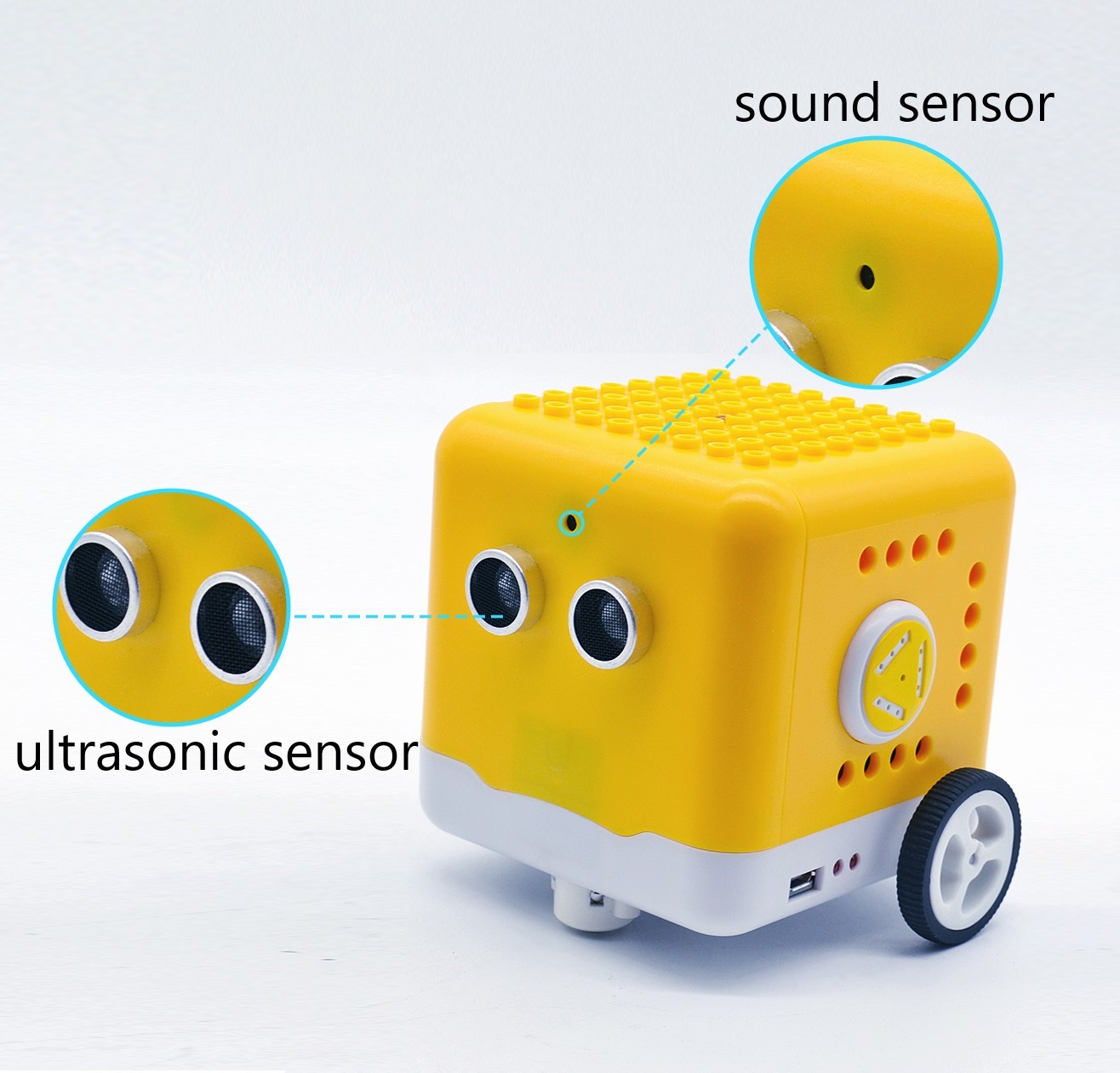
Sound Sensor
The sound sensor is a sensor that converts sound signals into electrical signals. It can be used to make sound-activated robots, sound-activated switches, sound-activated alarms, etc., according to the effect of interacting with the sound.
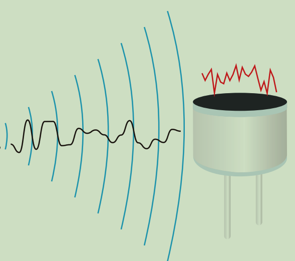
There is a very thin film in the sensor. When sound or air blows it,
the sound wave or airflow passes through, the film will vibrate
Continuously and generate an electrical signal, which is transmitted to the coding robot.
(Arduino Uno)
The sound intensity detected can be converted to any value between 0~1023.
The Trig pin of the ultrasonic sensor is connected to digital 2 and Echo pin is connected to digital 3; the sound sensor is interfaced with analog A0; SDA and SCL pin of dot matrix display is attached to analog A4 and A5; and the pin controlling direction on the left DC geared motor is connected to digital 8 and its pin controlling speed is interfaced with digital 9; the pin controlling direction on the right DC motor is attached to A1(digital 15) and the pin controlling speed is interfaced with digital 10.
Preparation
Slide the BT switch to OFF end
Connect the yellow robot to the computer by a USB cable(3)Upload test code on Arduino IDE
Test Code:
Note:
Need to fully charge the yellow robot if you continue further experiments.
Clap your hands or make sounds with 5cm away from sound sensor.
/*
kidsbits coding robot kit
Project 11
Sound-controlled Smart Car
http//www.kidsbits.cc
*/
#include <Matrix.h>
Matrix myMatrix(A4, A5);    //Instantiate an object myMatrix, and define the communication pins
volatile int distance;     //Ultrasonic ranging variable
volatile int distance1;
volatile int distance2;
int  sensorVal;
uint8_t LedArray1[8] = {0x00, 0x18, 0x24, 0x00, 0x00, 0xa5, 0xa5, 0x42};
uint8_t  LEDArray[8];  //Define an array variable without an initial value to facilitate the processing of multiple emoticon arrays

void front() {           //advance
  digitalWrite(8, LOW);
  digitalWrite(A1, LOW);
  analogWrite(9, 150);
  analogWrite(10, 150);
}

void back() {                 //move back
  digitalWrite(8, HIGH);
  digitalWrite(A1, HIGH);
  analogWrite(9, 150);
  analogWrite(10, 150);
}

void Stop() {               //Stop
  digitalWrite(8, HIGH);
  digitalWrite(A1, HIGH);
  analogWrite(9, 0);
  analogWrite(10, 0);
}

float checkdistance_2_3() {            //Ultrasonic ranging code
  digitalWrite(2, LOW);
  delayMicroseconds(2);
  digitalWrite(2, HIGH);
  delayMicroseconds(10);
  digitalWrite(2, LOW);
  float distance = pulseIn(3, HIGH) / 58.00;      //calculate distance
  delay(10);
  return distance;
}

 void left() {           //turn left
  digitalWrite(8, HIGH);
  digitalWrite(A1, LOW);
  analogWrite(9, 140);
  analogWrite(10, 140);
}


void right() {              //turn right
  digitalWrite(8, LOW);
  digitalWrite(A1, HIGH);
  analogWrite(9, 140);
  analogWrite(10, 140);
}

void avoid(){
  distance = checkdistance_2_3();       //Assign the distance value to distance
  if(distance < 15&&distance >0){
    Stop();              // Stop
    left();             //turn left
    delay(380);           //delay 380ms
    Stop();
    distance1 = checkdistance_2_3();   //Assign the value to distance1
    delay(300);                //delay 300ms
    right();                 //turn right
    delay(750);           //delay 750ms
    Stop();            // Stop
    distance2 = checkdistance_2_3();   //Assign the value to distance2
    delay(300);
    if (distance1 > distance2) {    //If the left is greater than the right
      left();
      delay(750);
      front();
    }else{
      front();
      }
  }
  else{
  front();
  }

}


void setup() {
  Serial.begin(9600);
  pinMode(8, OUTPUT);       //Define pin 8 to output
  pinMode(A1, OUTPUT);
  pinMode(2, OUTPUT);
  pinMode(3, INPUT);          //Define pin 3 to input
  distance = 0;
  distance1 = 0;
  distance2 = 0;
  myMatrix.begin(0x70);
  myMatrix.clear();
  delay(1000);
  for (int i = 0; i < 8; i++)
  {
    LEDArray[i] = LedArray1[i];
    for (int j = 7; j >= 0; j--)
    {
      if ((LEDArray[i] & 0x01) > 0)
        myMatrix.drawPixel(j, i, 1);
      LEDArray[i] = LEDArray[i] >> 1;
    }
  }
  myMatrix.writeDisplay();
}


void loop() {
  sensorVal = analogRead(A0);
  Serial.println(sensorVal);
  if(sensorVal > 150){
   for(int i=0;i<10;i++){
    avoid();
    delay(10);
  }
  }
  else{
    Stop();
  }
}
Test Result:
When the sound intensity is more than 150, the yellow robot will activate obstacle avoidance; when the sound intensity is less than 150, the robot will stop.
Project 12: Bluetooth Remote Control
Description:
Bluetooth wireless communication module has spread over in electronic sector.The Bluetooth standard has upgraded continuously so as to meet the needs of customers and technology.
Over the years, data transfer rates, power consumption of wearable devices and IoT devices, and security systems have promoted.
Parameter:
Working distance: In an open environment, achieve 30~50cm ultra-long-distance communication.
Working frequency: 2.4GHz ISM band.
Modulation method: GFSK (Gaussian Frequency Shift Keying)
Transmission power: -23dbm, -6dbm, 0dbm, 6dbm, which can be modified by AT command.
Sensitivity: ≤-84dBm at 0.1%BER
Transmission rate: 6K bytes
Security features: authentication and encryption
Support services: central and peripheral UUID FFE0, FFE1
Power consumption: automatic sleep mode,
Standby current 400uA~800uA, 8.5mA during transmission.
Power supply: 5V DC
Operating temperature: -5 to +50 degrees Celsius
Preparation
Slide the BT switch to OFF end.
Connect the yellow robot to the computer by a USB cable
Upload test code on Arduino IDE.
Test Code:
/*
kidsbits coding robot kit
Project 12-1
Bluetooth Remote Control
http//www.kidsbits.cc
*/
char ble_val; //A character variable that holds the value received by Bluetooth
void setup() {
  Serial.begin(9600);
}
void loop() {
  if (Serial.available() > 0) //Determine whether there is data in the serial port buffer area
  {
    ble_val = Serial.read();  //Read data from the serial port buffer
    Serial.println(ble_val);  //print
  }
}
//**********************************************************************
Test Result:
Upload test code, slide the Bluetooth switch to ON end and wait for the command from cellphone.
Download APP:
iOS system
Enter App store and search Coding Robot
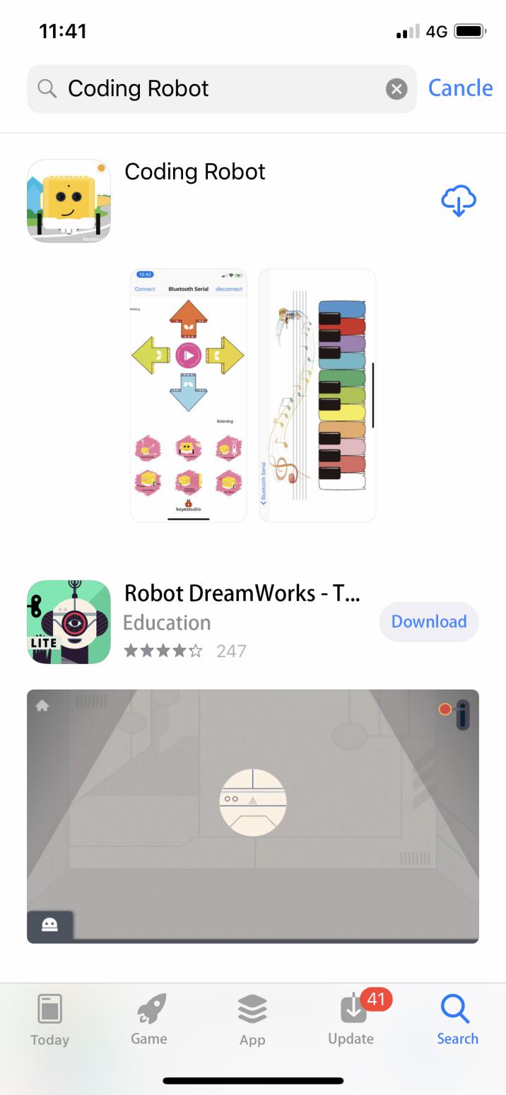
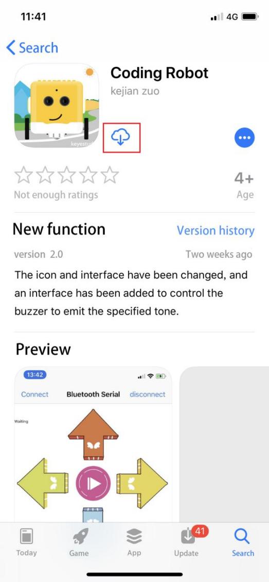
Download and open it.
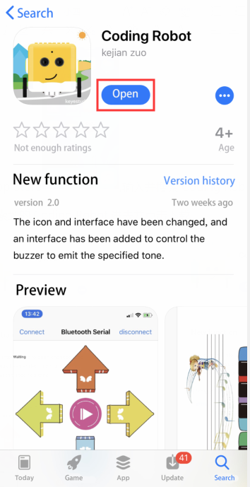
Coding Robot App:
Click“Connect”to pair with Bluetooth. Then
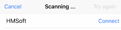 will pop up. Tap“Connect”again
to connect to Bluetooth.
will pop up. Tap“Connect”again
to connect to Bluetooth.
Android System:
Enter the following link to download App:
https://play.google.com/store/apps/details?id=com.keyestudio.codingrobot
Code Explanation:
Serial.available(): How many characters return to buffer area. This function is used to determine if there are data in the serial buffer area. When Serial.available()>0, the data is sent to the serial port.
Serial.read(): Refers to reading a Byte of data from the buffer of the serial port. For example, if a device sends data to the Arduino through the serial port, we can use Serial.read() to read the sent data.
Expansion Project:
We can connect an LED to the yellow robot and control the LED via App.
/*
kidsbits coding robot kit
Project 12-2
Bluetooth Control LED
http//www.kidsbits.cc
*/
int ledpin = 12;
void setup()
{
Serial.begin(9600);
pinMode(ledpin, OUTPUT);
}
void loop()
{
int i;
if (Serial.available())
{
i = Serial.read();
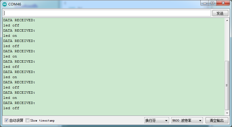
Serial.println("DATA RECEIVED:");
if (i == 'B')
{
digitalWrite(ledpin, HIGH);
Serial.println("led on");
}
if (i == 'S')
{
digitalWrite(ledpin, LOW);
Serial.println("led off");
}
}
}
*************************************************************************
Upload code, click  on App to
control the LED on and off
on App to
control the LED on and off
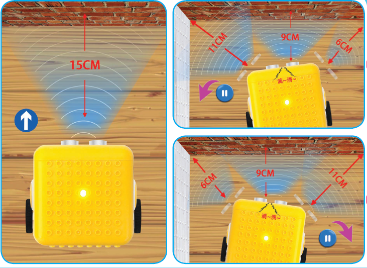
Project 13: Bluetooth remote robot
Description:
We’ve learned the basic knowledge of Bluetooth. And in this lesson, we will make a Bluetooth remote smart car. In this experiment, we default the HM-10 Bluetooth module as a Slave and the cellphone as a Host.
And we also need to install an App to control this yellow robot.
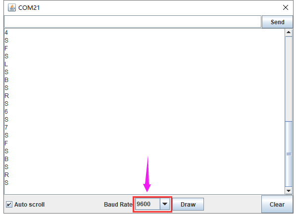
Slide the Bluetooth switch to OFF end, upload test code, slide BT switch to ON end, then open serial monitor and set baud rate to 9600. As shown below:
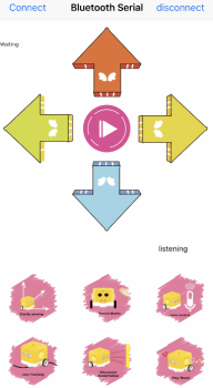
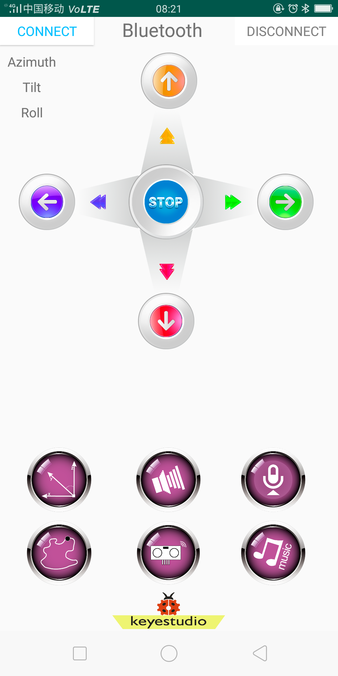
Functions of App icons:
|
Pairing Bluetooth |
|
|---|---|---|
|
Enter Bluetooth control interface |
|
|
Disconnect Bluetooth |
|
|
Press it to output F; Release it to output S |
Go forward Stop |
|
Press it to output B; Release it to output S |
Go back Stop |
|
Press it to output L; Release it to output S |
Turn left Stop |
|
Press it to output R; Release it to output S |
Turn right Stop |
|
Press it to output S; Release it to output S |
End functions |
|
Press it to send Y Release it to send Y; |
Sound -controlled function will be activated. |
|
“Waiting” label on the top left corner changes into beating bytes |
Beating bytes means starting device. |
|
Press it to output X; Release it to send X; |
Start line tracking function; |
|
Press it to output U; Release it to send U; |
Start following function; |
|
|
|
|
Press it to emit “do1”, Release it to send S |
|
|
Press it to emit“re1”, Release it to send S |
|
|
Press it to emit“mi1”, Release it to send S |
|
|
Press it to emit“fa1”, Release it to send S |
|
|
Press it to emit “so”, Release it to send S |
|
|
Press it to emit “la”, Release it to send S |
|
|
Press it to emit“si”, Release it to send S |
|
|
Press it to emit“do2”, Release it to send S |
|
|
Press it to emit“re2”, Release it to send S |
|
|
Press it to emit “mi2”, Release it to send S |
|
|
Press it to emit“fa2”, Release it to send S |
|
|
Send P,buzzer will play music |
|
|
Press HMSoft to return the main page |


Preparation
Slide the BT switch to OFF end.
Connect the yellow robot to the computer by a USB cable(3)Upload test code on Arduino IDE.
Test Code:
/*
kidsbits coding robot kit
Project 13
Bluetooth remote robot
http//www.kidsbits.cc
*/
#include <Matrix.h>

volatile char val;

Matrix myMatrix(A4,A5);
void Front() {   //advance
  digitalWrite(8,LOW);
  digitalWrite(A1,LOW);
  analogWrite(9,200);
  analogWrite(10,200);
}

void Back() {     //move back
  digitalWrite(8,HIGH);
  digitalWrite(A1,HIGH);
  analogWrite(9,194);
  analogWrite(10,200);
}

uint8_t LedArray1[8]={0x18,0x18,0x18,0x18,0x99,0x5a,0x3c,0x18};
uint8_t  LEDArray[8];
uint8_t LedArray2[8]={0x18,0x3c,0x5a,0x99,0x18,0x18,0x18,0x18};
uint8_t LedArray3[8]={0x08,0x04,0x02,0xff,0xff,0x02,0x04,0x08};
uint8_t LedArray4[8]={0x10,0x20,0x40,0xff,0xff,0x40,0x20,0x10};
uint8_t LedArray5[8]={0x18,0x18,0x00,0x18,0x18,0x18,0x18,0x18};
void Left() {   //turn left
  digitalWrite(8,HIGH);
  digitalWrite(A1,LOW);
  analogWrite(9,120);
  analogWrite(10,120);
}

void Right() {      //turn right
  digitalWrite(8,LOW);
  digitalWrite(A1,HIGH);
  analogWrite(9,120);
  analogWrite(10,120);
}

void Stop() {     //  Stop
  digitalWrite(8,HIGH);
  digitalWrite(A1,HIGH);
  analogWrite(9,0);
  analogWrite(10,0);
}

void setup(){
  Serial.begin(9600);
  val = 0;
  myMatrix.begin(0x70);
  myMatrix.clear();
  myMatrix.writeDisplay();
  pinMode(8, OUTPUT);
  pinMode(A1,OUTPUT);
}

void loop(){
  if (Serial.available() > 0) {   //Determine whether there is data in the serial port buffer area
    val = Serial.read();          //Read data from the serial port buffer
    Serial.println(val);           //print

  }
  switch (val) {
   case 'F':
    Front();
    myMatrix.clear();
    myMatrix.writeDisplay();
    for(int i=0; i<8; i++)
    {
      LEDArray[i]=LedArray1[i];
      for(int j=7; j>=0; j--)
      {
        if((LEDArray[i]&0x01)>0)
        myMatrix.drawPixel(j, i,1);
        LEDArray[i] = LEDArray[i]>>1;
      }
    }
    myMatrix.writeDisplay();
    break;
   case 'B':
    Back();
    myMatrix.clear();
    myMatrix.writeDisplay();
    for(int i=0; i<8; i++)
    {
      LEDArray[i]=LedArray2[i];
      for(int j=7; j>=0; j--)
      {
        if((LEDArray[i]&0x01)>0)
        myMatrix.drawPixel(j, i,1);
        LEDArray[i] = LEDArray[i]>>1;
      }
    }
    myMatrix.writeDisplay();
    break;
   case 'L':
    Left();
    myMatrix.clear();
    myMatrix.writeDisplay();
    for(int i=0; i<8; i++)
    {
      LEDArray[i]=LedArray3[i];
      for(int j=7; j>=0; j--)
      {
        if((LEDArray[i]&0x01)>0)
        myMatrix.drawPixel(j, i,1);
        LEDArray[i] = LEDArray[i]>>1;
      }
    }
    myMatrix.writeDisplay();
    break;
   case 'R':
    Right();
    myMatrix.clear();
    myMatrix.writeDisplay();
    for(int i=0; i<8; i++)
    {
      LEDArray[i]=LedArray4[i];
      for(int j=7; j>=0; j--)
      {
        if((LEDArray[i]&0x01)>0)
        myMatrix.drawPixel(j, i,1);
        LEDArray[i] = LEDArray[i]>>1;
      }
    }
    myMatrix.writeDisplay();
    break;
   case 'S':
    Stop();
    myMatrix.clear();
    myMatrix.writeDisplay();
    for(int i=0; i<8; i++)
    {
      LEDArray[i]=LedArray5[i];
      for(int j=7; j>=0; j--)
      {
        if((LEDArray[i]&0x01)>0)
        myMatrix.drawPixel(j, i,1);
        LEDArray[i] = LEDArray[i]>>1;
      }
    }
    myMatrix.writeDisplay();
    break;
  }

}
Test Result
Upload code, open switches under the yellow robot and pair with Bluetooth. Then you can control this robot through App.
Project 14: Control Robot by APP
Description:
In this project, we will control the yellow robot via App. You can make it perform all functions
Preparation
Slide the BT switch to OFF end
Connect the yellow robot to the computer with a USB cable.(3)Upload test code on Arduino IDE
Test Code:
Turn off the BT switch before uploading test code
/*
kidsbits coding robot kit
Project 14
Control Robot by APP
http//www.kidsbits.cc
*/
#include <Matrix.h>

volatile char val;
volatile int distance1;
volatile int val_L;
volatile int val_R;
volatile int distance2;
volatile int distance3;
volatile int distance4;
volatile int sound1;
volatile int flag;

Matrix myMatrix(A4, A5);     //Instantiate an object myMatrix, and define the communication pins
void Front() {                //advance
  digitalWrite(8,LOW);
  digitalWrite(A1,LOW);
  analogWrite(9,140);
  analogWrite(10,140);
}

void Left() {                 //advance and turn left
  digitalWrite(8, LOW);
  digitalWrite(A1, LOW);
  analogWrite(9, 100);
  analogWrite(10, 180);
}

void Left2() {             //turn left
  digitalWrite(8, HIGH);
  digitalWrite(A1, LOW);
  analogWrite(9, 120);
  analogWrite(10, 120);
}

void Back() {                //move back
  digitalWrite(8,HIGH);
  digitalWrite(A1,HIGH);
  analogWrite(9,149);
  analogWrite(10,150);
}

void Right() {                //advance and turn right
  digitalWrite(8, LOW);
  digitalWrite(A1, LOW);
  analogWrite(9, 180);
  analogWrite(10, 100);
}

void Right2() {            //turn right
  digitalWrite(8, LOW);
  digitalWrite(A1, HIGH);
  analogWrite(9, 120);
  analogWrite(10, 120);
}

void Stop() {                  //Stop
  digitalWrite(8, HIGH);
  digitalWrite(A1, HIGH);
  analogWrite(9, 0);
  analogWrite(10, 0);
}
//LCD dot matrix displays code
uint8_t LedArray1[8] = {0x18, 0x18, 0x18, 0x18, 0x99, 0x5a, 0x3c, 0x18};
uint8_t  LEDArray[8];
uint8_t LedArray2[8] = {0x18, 0x3c, 0x5a, 0x99, 0x18, 0x18, 0x18, 0x18};
uint8_t LedArray4[8] = {0x08, 0x04, 0x02, 0xff, 0xff, 0x02, 0x04, 0x08};
uint8_t LedArray3[8] = {0x10, 0x20, 0x40, 0xff, 0xff, 0x40, 0x20, 0x10};
uint8_t LedArray5[8] = {0x18, 0x18, 0x00, 0x18, 0x18, 0x18, 0x18, 0x18};
float checkdistance_2_3() {        //ultrasonic ranging
  digitalWrite(2, LOW);
  delayMicroseconds(2);
  digitalWrite(2, HIGH);
  delayMicroseconds(10);
  digitalWrite(2, LOW);
  float distance = pulseIn(3, HIGH) / 58.00;     //calculate distance
  delay(10);                           //  delay
  return distance;
}

void follow() {
  flag = 0;
  while (flag == 0) {
    distance1 = checkdistance_2_3();
    if (distance1 > 20 && distance1 < 40) {
      Front();

    } else if (distance1 > 15 && distance1 <= 20) {
      Stop();
    } else if (distance1 > 0 && distance1 <= 15) {
      Back();
    } else if (distance1 > 40) {
      Stop();
    }
    if (Serial.available() > 0) {
      val = Serial.read();
      if (val == 'S') {
        flag = 1;

      }

    }
  }
}

void tracking() {
  flag = 0;
  while (flag == 0) {
    val_L = digitalRead(4);
    val_R = digitalRead(5);
    if (val_L == 0 && val_R == 1) {
      Left();

    } else if (val_L == 1 && val_R == 0) {
      Right();
    } else if (val_L == 1 && val_R == 1) {
      Stop();
    } else {
      Front();

    }
    if (Serial.available() > 0) {
      val = Serial.read();
      if (val == 'S') {
        flag = 1;

      }

    }
  }
}

void avoid(){
  distance4 = checkdistance_2_3();       //Assign the distance value to distance
  if(distance4 < 15&&distance4 >0){
    Stop();              //Stop
    Left2();             //turn left
    delay(380);           //delay 380ms
    Stop();
    distance1 = checkdistance_2_3();   //Assign the value to distance1
    delay(300);                //delay 300ms
    Right2();                 //turn right
    delay(750);           //delay 750ms
    Stop();            //Stop
    distance2 = checkdistance_2_3();   //Assign the value to distance2
    delay(300);
    if (distance1 > distance2) {    //If the left is greater than the right
      Left2();
      delay(750);
      Front();
    }else{
      Front();
      }
  }
  else{
  Front();
  }

}


void sound() {
  flag = 0;
  while (flag == 0) {
    sound1 = analogRead(A0);
    if (sound1 > 150) {
       for(int i=0;i<10;i++){
    avoid();
    delay(10);
  }
  }
  else{
    Stop();
  }
    if (Serial.available() > 0) {
      val = Serial.read();
      if (val == 'S') {
        flag = 1;

      }

    }
  }
}

void music123() {                //Birthday song code
  flag = 0;
  while (flag == 0) {
    tone(6, 392);
    delay(125);
    tone(6, 392);
    delay(125);
    tone(6, 440);
    delay(250);
    tone(6, 392);
    delay(250);
    tone(6, 532);
    delay(250);
    tone(6, 494);
    delay(500);
    tone(6, 392);
    delay(125);
    tone(6, 392);
    delay(125);
    tone(6, 440);
    delay(250);
    tone(6, 392);
    delay(250);
    tone(6, 587);
    delay(250);
    tone(6, 532);
    delay(500);
    tone(6, 392);
    delay(125);
    tone(6, 392);
    delay(125);
    tone(6, 784);
    delay(250);
    tone(6, 659);
    delay(250);
    tone(6, 532);
    delay(250);
    tone(6, 494);
    delay(250);
    tone(6, 440);
    delay(250);
    tone(6, 392);
    delay(125);
    tone(6, 392);
    delay(125);
    tone(6, 330);
    delay(250);
    tone(6, 262);
    delay(250);
    tone(6, 587);
    delay(250);
    tone(6, 532);
    delay(500);
    noTone(6);
    flag = 1;
    val = 'S';
  }
}

void setup() {
  Serial.begin(9600);
  val = 0;
  distance1 = 0;
  val_L = 0;
  val_R = 0;
  distance2 = 0;
  distance3 = 0;
  distance4 = 0;
  sound1 = 0;
  flag = 0;
  myMatrix.begin(0x70);

  myMatrix.clear();
  myMatrix.clear();
  myMatrix.writeDisplay();
  pinMode(8, OUTPUT);
  pinMode(A1, OUTPUT);
  pinMode(6, OUTPUT);
  pinMode(2, OUTPUT);
  pinMode(3, INPUT);
  pinMode(4, INPUT);
  pinMode(5, INPUT);

}

void loop() {
  if (Serial.available() > 0) {
    val = Serial.read();
    Serial.println(val);

  }
  switch (val) {
    case 'F':
      Front();
      myMatrix.clear();
      myMatrix.writeDisplay();
      for (int i = 0; i < 8; i++)
      {
        LEDArray[i] = LedArray1[i];
        for (int j = 7; j >= 0; j--)
        {
          if ((LEDArray[i] & 0x01) > 0)
            myMatrix.drawPixel(j, i, 1);
          LEDArray[i] = LEDArray[i] >> 1;
        }
      }
      myMatrix.writeDisplay();
      break;
    case 'B':
      Back();
      myMatrix.clear();
      myMatrix.writeDisplay();
      for (int i = 0; i < 8; i++)
      {
        LEDArray[i] = LedArray2[i];
        for (int j = 7; j >= 0; j--)
        {
          if ((LEDArray[i] & 0x01) > 0)
            myMatrix.drawPixel(j, i, 1);
          LEDArray[i] = LEDArray[i] >> 1;
        }
      }
      myMatrix.writeDisplay();
      break;
    case 'L':
      Left();
      myMatrix.clear();
      myMatrix.writeDisplay();
      for (int i = 0; i < 8; i++)
      {
        LEDArray[i] = LedArray4[i];
        for (int j = 7; j >= 0; j--)
        {
          if ((LEDArray[i] & 0x01) > 0)
            myMatrix.drawPixel(j, i, 1);
          LEDArray[i] = LEDArray[i] >> 1;
        }
      }
      myMatrix.writeDisplay();
      break;
    case 'R':
      Right();
      myMatrix.clear();
      myMatrix.writeDisplay();
      for (int i = 0; i < 8; i++)
      {
        LEDArray[i] = LedArray3[i];
        for (int j = 7; j >= 0; j--)
        {
          if ((LEDArray[i] & 0x01) > 0)
            myMatrix.drawPixel(j, i, 1);
          LEDArray[i] = LEDArray[i] >> 1;
        }
      }
      myMatrix.writeDisplay();
      break;
    case 'S':
      Stop();
      myMatrix.clear();
      myMatrix.writeDisplay();
      for (int i = 0; i < 8; i++)
      {
        LEDArray[i] = LedArray5[i];
        for (int j = 7; j >= 0; j--)
        {
          if ((LEDArray[i] & 0x01) > 0)
            myMatrix.drawPixel(j, i, 1);
          LEDArray[i] = LEDArray[i] >> 1;
        }
      }
      myMatrix.writeDisplay();
      noTone(6);
      break;
    case 'U':
      follow();
      break;
    case 'X':
      tracking();
      break;
    case 'Y':
      sound();
      break;
    case '1':
      tone(6, 262);
      break;
    case '2':
      tone(6, 294);
      break;
    case '3':
      tone(6, 330);
      break;
    case '4':
      tone(6, 349);
      break;
    case '5':
      tone(6, 392);
      break;
    case '6':
      tone(6, 440);
      break;
    case '7':
      tone(6, 494);
      break;
    case '8':
      tone(6, 532);
      break;
    case 'G':
      tone(6, 587);
      break;
    case 'H':
      tone(6, 659);
      break;
    case 'J':
      tone(6, 698);
      break;
    case 'P':
      music123();
      break;
  }

}
Test Result:
Upload code, open switches under the yellow robot and pair with Bluetooth. Then you can control this robot through App.